Version 16.10 AF-6600 AF-5000 Series Install Manual 80
P/N: 73102 Dynon GPS-250 Antenna Module
P/N: 73120 Dynon GPS-220 Antenna Module
Physical Installation
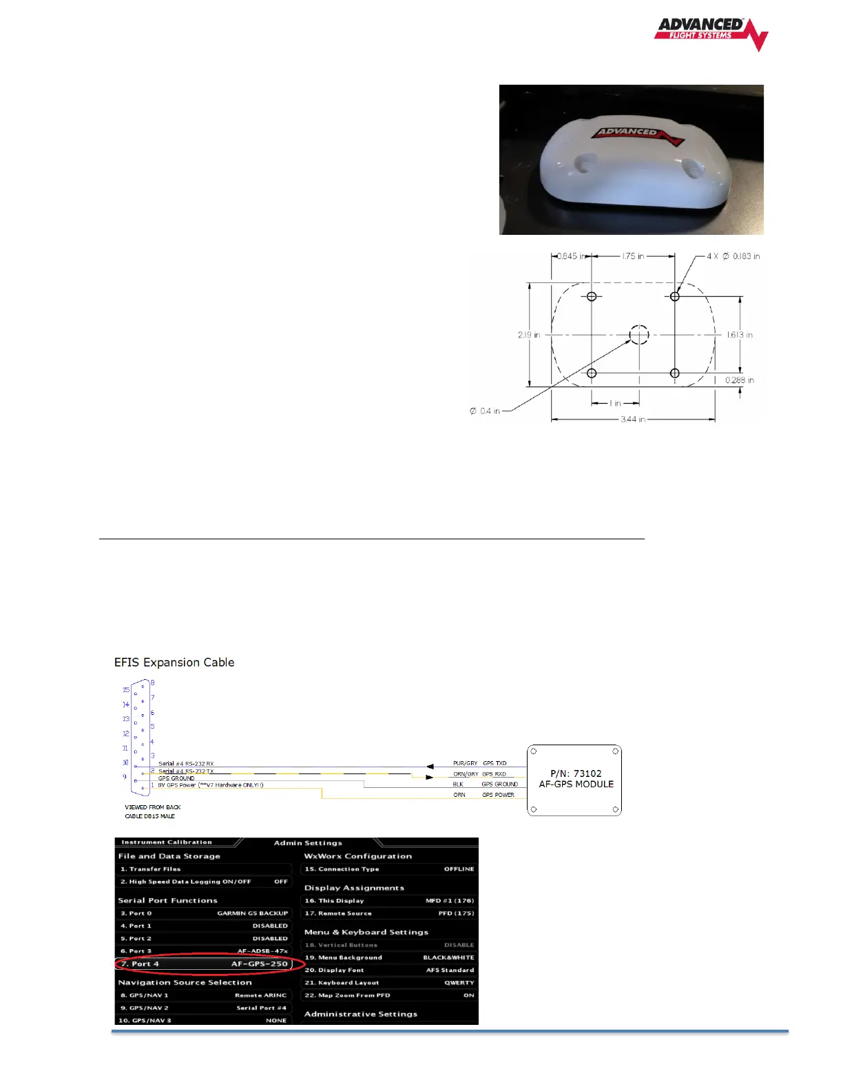
The diagram below shows the mounting dimensions of the GPS
module. Note that it utilizes a common bolt pattern found in much
of general aviation.
Mounting hardware is not included. The 73102 Dynon GPS-250 or
73120 GPS-2020 Antenna Module is designed to work with #8
fasteners with 100 degree countersunk heads. The use of nut
plates is recommended for convenience, but other hardware
can be used if space allows. Specific hardware selection is
determined by the installer. We recommend you use weather
sealant around the fastener heads to keep moisture from
entering the aircraft through the mounting holes. The module
itself is sealed and includes a rubber gasket that seals the
inner wire hole. It also allows the module to be mounted on
slightly curved surfaces. For extra protection, you may use
weather sealant around the outside of the AF-GPS Antenna
Module where it meets the skin of the aircraft.
The GPS Module includes 18 feet of wire for connection to the EFIS display. The GPS Module can be connected to any
available EFIS serial port.
The GPS module uses a dedicated power pin on AF-6600 or AF-5000 EFIS Expansion 15 pin connector.
GPS-250/2020 GPS Description EFIS Connection PIN EFIS Description
ORANGE Power EFIS Expansion 1 8V Power
BLACK Ground EFIS Expansion 9 GPS Ground
PURPLE/GRAY GPS TXD RS-232 RXD
ORANGE/GRAY GPS RXD RS-232 TXD