Version 16.10 AF-6600 AF-5000 Series Install Manual 152
Manifold Pressure Transducer Installation
The manifold pressure transducer should be mounted on the firewall or in the cabin area. The transducer
port is connected to the engine manifold pressure port with a ¼” ID hose and hose clamp. The manifold
pressure port location can be found in the engine manual.
P/N Pressure Application
41400 30 In-Hg Old AFS Sensor for Normally Aspirated Engine
41401 59 In-Hg Current Sensor (Normal and Turbo Engine)
We used the following fittings to connect the transducer in our aircraft:
AN823-4 45 deg pipe to 37 deg flare fitting
471-4D 37 deg flare fitting for hose
306-4 ¼” ID Black Hose
The transducer wires should be connected from the harness to the transducer using the supplied
Weatherpack connector.
For information on crimping the Weatherpack pins:
http://www.weatherpack.com
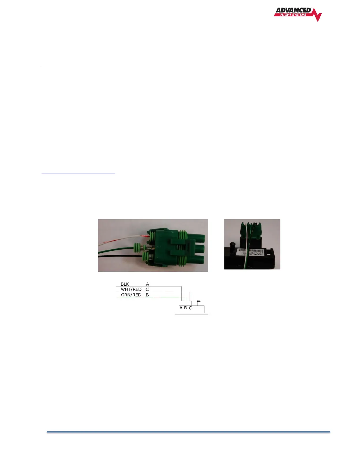
The Weatherpack connector comes with three pins, three rubber seals, and a connector housing. Slide the
three rubber seals onto the three wires and the pins onto the ends of the wires. Crimp the 3 pins onto the
ends of the wires, ensuring that the long tabs that cradle the rubber
seal wrap around the seal.
Manifold Sensor Connections:
Pin 18 WHT/RED +5V C
Pin 26 GRN/RED Signal (4.5V - .5V) B
Pin 17 Black Ground A