Version 16.10 AF-6600 AF-5000 Series Install Manual 147
Amp Transducer Installation
Shunt Transducer
Mount the Shunt amp transducer to a stationary location in the main power wire from the Alternator.
The Shunt Amp transducer wires should be connected from the harness to the transducer by crimping two
standard #8 ring terminal to the wires.
Pin 24 Orange/Green + Alternator Side
Pin 25 Orange/Purple - Battery Side
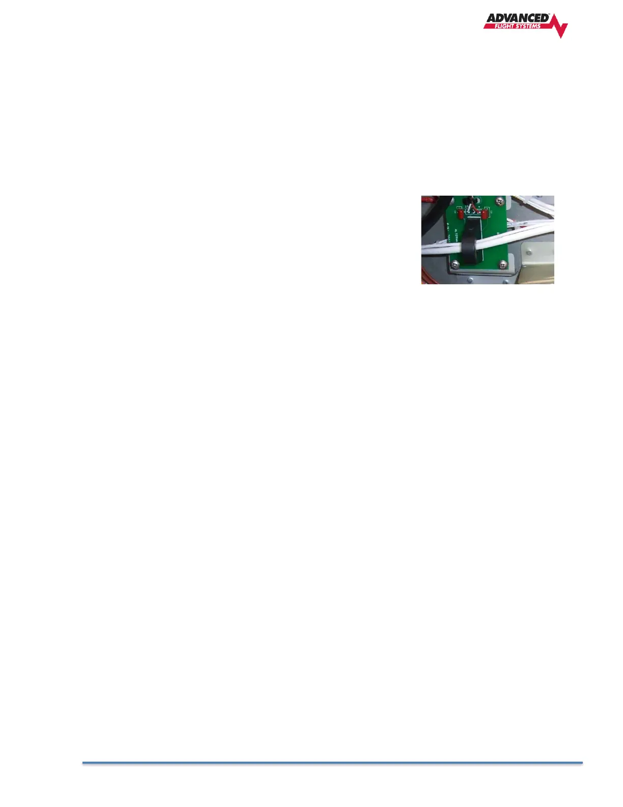
P/N: 44100 Optional Hall Effect Transducer (Used for dual Alternator
Systems)
Mount the amp transducer in the cabin area to a stationary location. The
amp transducer board should be mounted so that the bottom of the circuit
board does not touch any metal. The amp transducer is designed to
measure the current in the wire from the alternator. The wire from the
alternator must pass through the transducer in the proper direction; the
board is marked alternator on one side and battery on the other. Male D-
sub pins will need to be crimped onto the transducer wires.
CAUTION: Always ground yourself before wiring.
Pin 15 +8V RED
Pin 31 Signal ORN/WHT
Pin 13 Ground Black