Version 16.10 AF-6600 AF-5000 Series Install Manual 155
Trim & Flap Position Installation
If you are using the ACM module do not connect the Flap
and Trim transducers to the SV-EMS-220, they will
connect to the ACM Flap and Trim Harness.
The system is designed to read the position transducer that is
in the MAC trim servo. The MAC servo has 5 wires. The two
white wires are for motor operation and the color-striped wires
are for the position transducer.
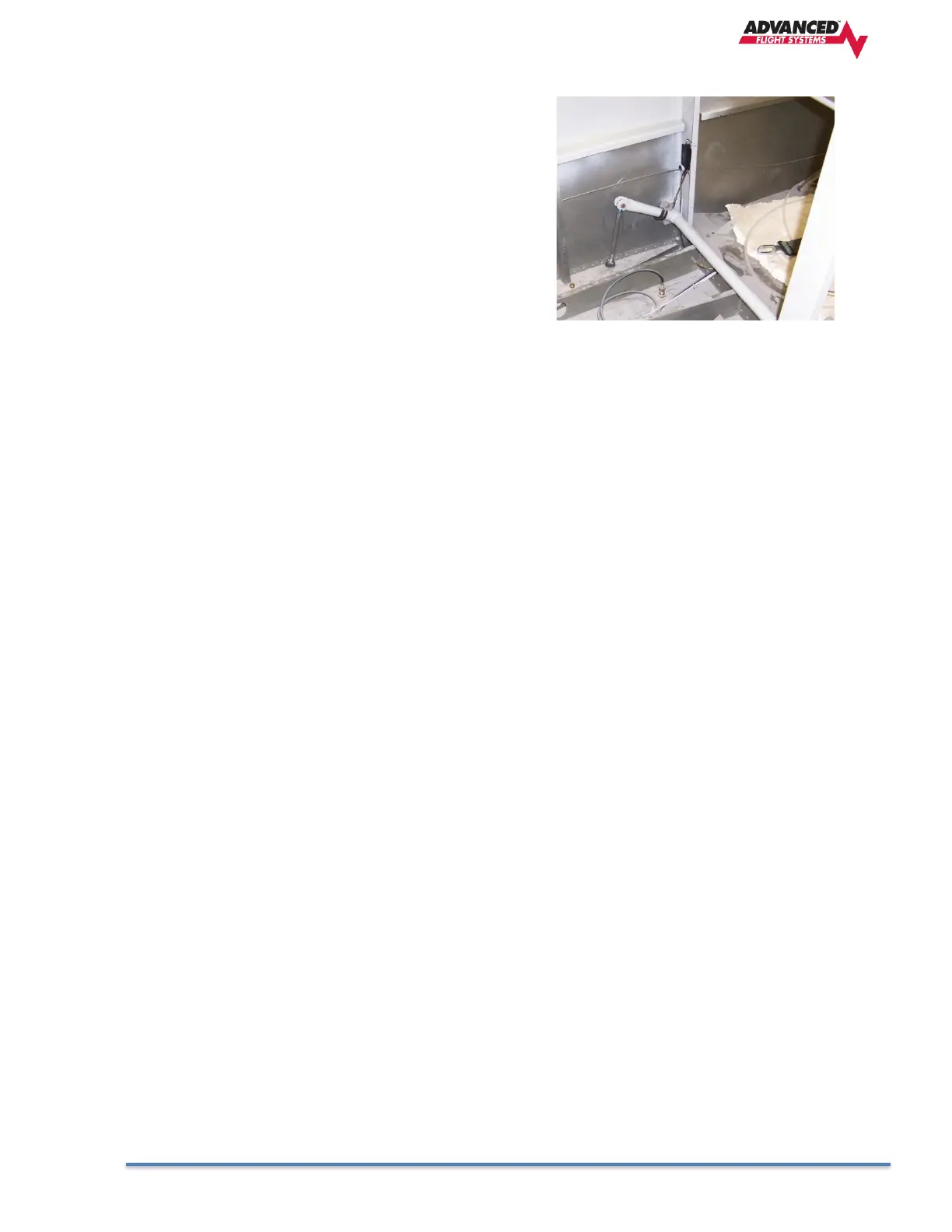
The flap position can be measured by using the MAC linear
position sensor P/N: POS-12
http://www.rayallencompany.com/products/indsens.html
CAUTION: DO NOT connect the MAC indicators and the AF-
5500/5600 the MAC trim servos. The MAC trim indicators are
+12V and the EFIS screens are +5V. The power and ground wires connect to all the servo’s.
CAUTION: Verify before turning the system on the trim servo wiring is correct. If the +5V or Ground
connection is wired to the WHT/GRN wire on a servo, it could damage the servo.
Note: Trim & Flap Positions MUST be calibrated. See the Instrument Calibration section.