Version 16.10 AF-6600 AF-5000 Series Install Manual 150
Fuel Flow Transducer Installation
The inlet and outlet ports in the fuel flow transducer
have ¼” NPT threads. Use only ¼” NPT hose or pipe
fittings to match. When assembling fittings into the inlet
and outlet ports DO NOT EXCEED a torque of 180 inch
lbs, or screw the fittings in more than 2 full turns past
hand tight WHICHEVER HAPPENS FIRST. AFS will
not be responsible for cracked castings caused by
failure to use ¼” NPT fittings, over-torqueing the fittings,
or assembling them beyond the specified depth. Use
only aircraft FUEL LUBE on the NPT fittings; NEVER
USE TEFLON TAPE or SILICON SEALER IN AN
AIRCRAFT FUEL SYSTEM.
A screen or filter should be installed upstream of the flow transducer to screen out debris which could affect
rotor movement or settle in the V-bearings.
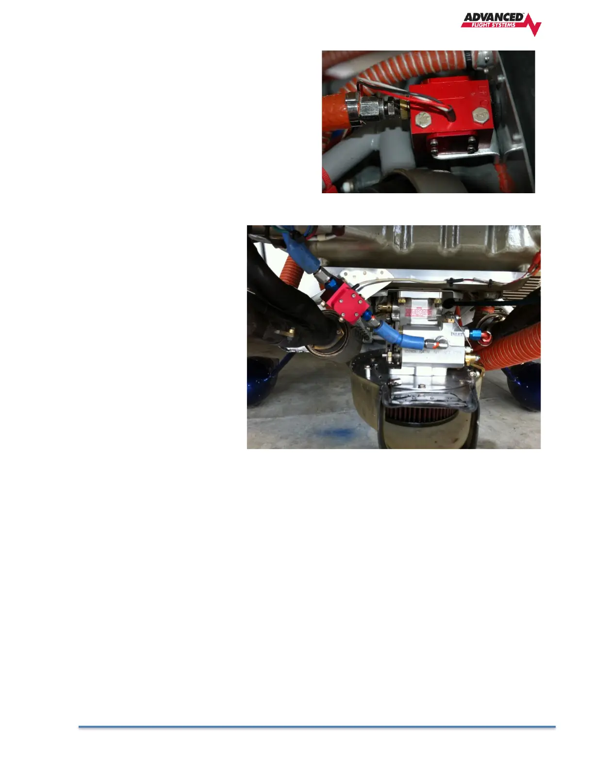
Mount the fuel flow transducer in a
position so the three wire leads are
pointed straight up. Use only smooth
radius curves in the fuel line and place
the transducer with 5” of straight line
before and after. The transducer wires
should be connected directly to the 37-
pin D-SUB using the cable provided.
The transducer should be mounted
according to the fuel metering device
manufacturer’s recommendations.
AFS has seen good results with the
following mounting:
1. The transducer in a stationary
location in-line between the
electric boost pump and the
engine driven pump.
2. The transducer in a stationary location in-line between the fuel injection servo and the distribution
block.
3. The transducer in a stationary location in-line between the Engine driven pump and the Carburetor.
NOTE: The Electronics International FT-60 (Red Cube) transducer is rated for .6 – 70+ GPH. AFS
recommends that the Electronics International FT-90 (Gold Cube) transducer be used for applications
requiring more than 35 GPH (350HP) or for gravity flow fuel systems without a fuel pump (Contact AFS to
exchange transducers).
CAUTION: NEVER CONNECT THE FUEL FLOW TRANSDUCER DIRECTLY TO THE ENGINE WITHOUT
COVERING WITH FIRE SLEEVE.
The Fuel Flow transducer wires should be connected from the harness to the transducer using the supplied
connectors.
Pin 15 Red +8V
Pin 14 Yellow Signal
Pin 13 Black Ground