Version 16.10 AF-6600 AF-5000 Series Install Manual 135
Engine Tachometer (RPM)
The EFIS will display RPM from either the RPM Input Left or the RPM Input Right, whichever is noticed by
the SV-EMS-220 first. If the first RPM signal is lost (such as when one ignition source fails, or during a
routine mag check), then EFIS will display RPM from the remaining RPM signal. If your engine only provides
one RPM signal, connect it to one of the two RPM Input Left pins.
Pin 32 and Pin 34 are both LEFT RPM input. Use one, or the other, but not both.
Pin 33 and Pin 35 are both RIGHT RPM input. Use one, or the other, but not both.
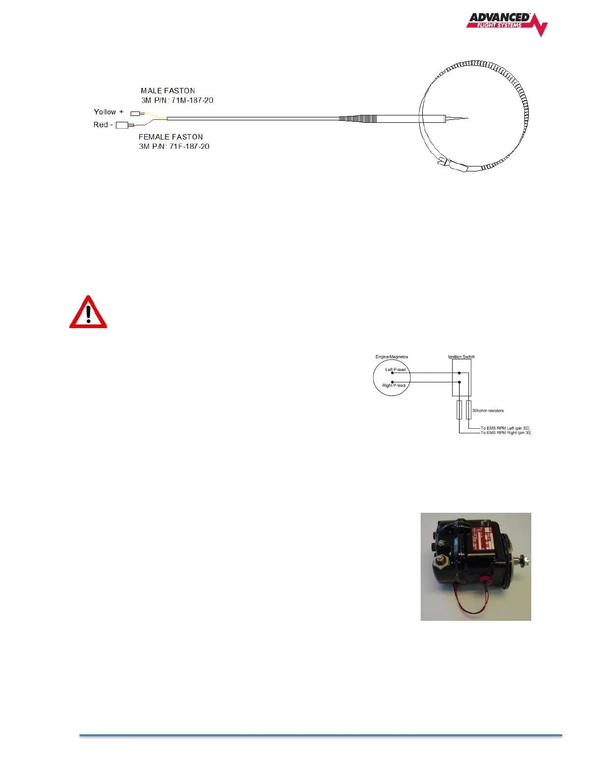
P-lead pickoff (Lycoming and Continental)
If you do not have a dedicated tachometer pickoff, you must follow
the instructions below.
Use the two included 30 kΩ resistors (color bands: orange, black,
brown, red, brown; connect in either direction) to attach left and
right P-leads to the standard RPM Left and RPM Right inputs on
the SV-EMS-220/221. It is important to connect each resistor as
close as possible to the spot where you tap into the P-lead. This minimizes the length of cable carrying high
voltage spikes. Six-cylinder Lycoming engines sometimes need more inline resistance to prevent false
readings by the SV-EMS-220/221. If you supply your own resistors, they need not be exactly 30 kΩ.
Additionally, both 1/4W and 1/2W resistors are acceptable to use.
Optional Mag RPM Sensor Installation
The AFS Hall Effect Sensor P/N: 43100 can be used with the SV-EMS-220
module as long as you have a 5k resistor between the red and white wires.
All P/N: 43100 sensors shipped after 1/1/2023 have a built-in pull up resistor
and don’t need the external resistor.
The RPM sensor should be installed in the non-impulse coupled magneto if
possible (Engines with one electronic ignition should install the sensor in the
impulse mag). The correct magneto can be found in the engine manual. The
sensor is screwed into the magnet vent port nearest the magneto-mounting
flange where the magneto attaches to the engine. Replace the existing vent plug with the sensor. The RPM
sensor wires should be connected to the Engine Harness with Fast On Terminals, Butt Connectors or with
solder and heat shrink. If using one mag and one electronic ignition, use the mag sensor for RPM input, as
long as the mag is turning, RPM will be displayed even with the mag turned off.
The RED sensor is for Slick Mags and the BLUE sensor is for Bendix mags.