Version 16.10 AF-6600 AF-5000 Series Install Manual 11
1 INSTALLATION PLANNING
This section will provide an overview of the electrical interconnect wiring and mechanical components needed to install
an AF-6600 or AF-5000 based system. It is recommended that you become familiar with this section before starting the
actual installation in the aircraft.
1.1 System Architecture
A complete AF-6600 / AF-5000 based avionics system will have multiple components that are all connected together to
share data and in some cases electrical power. Some of the components will be mounted in the instrument panel and
some will be remote mounted, in some cases AFS offers a remote or panel mounted version. The PMA450 Audio Panel
or SV-COM-T25 radio have a remote or panel mounted option. When you install avionics in an aircraft you will need to
wire to an avionics power bus with circuit protection and connect to different types of data buses so all the equipment can
talk with each other. There are five different data buses that are commonly used in aircraft. Properly planning and wiring
all the equipment can be time consuming and complicated.
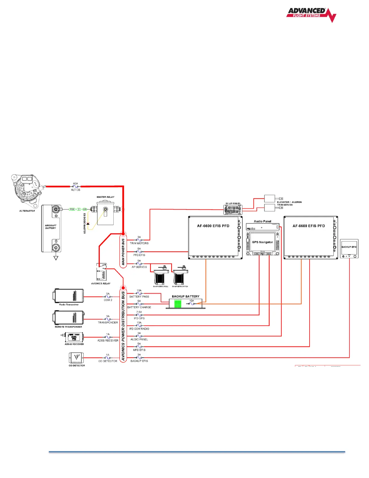
1.2 Avionics Power Bus
Most aircraft have an Avionics Power Bus that is connected to the aircraft Main Power Bus with a high current relay. The
avionics bus relay is controlled by a panel mounted AVIONICS switch. The Pilot side EFIS PFD should be wired to the
aircraft Main Power Bus so it can display engine data during an engine start. Once the engine and alternator are running
switching on the panel mounted AVIONICS switch will power the rest of the avionics.
Recommended Aircraft Power Wire Size