Version 16.10 AF-6600 AF-5000 Series Install Manual 136
CAUTION: Do not route RPM sensor wires with Magneto P leads or electron ignition wiring. Most Magnetos
have two ports on opposite sides, one near the plug wires and one near the drive shaft. The sensor needs to
be mounted in the port closest to the drive shaft.
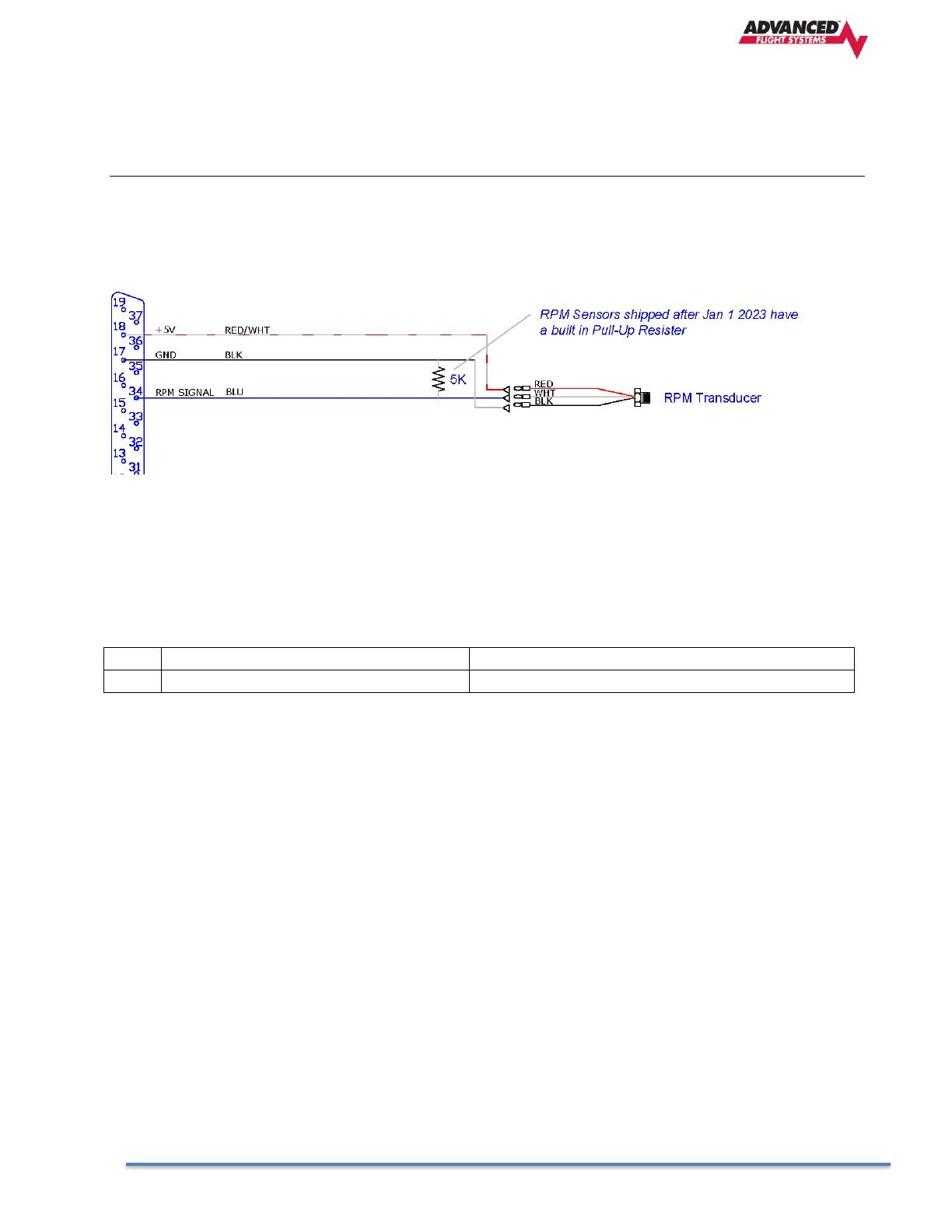
HARNESS Signal SENSOR WIRE
Pin 18 Red/White +5V RED
Pin 34 Blue Signal WHT
Pin 17 Black Ground BLK
ELECTRONIC IGNITIONS
EMAGS
If using EMAG’s you should connect the EMAG tach signal to input pin 32 or 33 without a resistor. An EMAG
will output the tach signal even when turned OFF so you only need to connect a single EMAG to the SV-
EMS-220
Lightspeed Ignitions
RPM Signal Connection
+12V signal, connect to SV-EMS standard RPM inputs without resistor
SV-EMS Pins
32 White/Green Standard RPM LEFT
33 White/Blue Standard RPM Right
ShureFly – Lycoming EIS Ignitions
RPM Signal Connection
Requires SureFly RPM TACH2 Tachometer Signal Converter
+5V signal, connect to SV-EMS Low voltage RPM inputs without resistor
SV-EMS Pins
34 Blue Low Voltage RPM LEFT
35 Green Low Voltage RPM Right