Version 16.10 AF-6600 AF-5000 Series Install Manual 121
Antenna BNC Connector
This section describes the technique for attaching the antenna cable to a BNC connector. A BNC
connector is not supplied with the AF-ADSB. The AF-ADSB has a female BNC connection. Therefore,
you will need to source a male BNC connector that is compatible with the antenna cable type that
meets your aircraft’s needs.
A dual crimp style BNC connector can be completed using a wide range of commercial crimp tools (for
example the Tyco 5-1814800-3). The die apertures for the inner pin and the outer shield should be
approximately 1.72 mm and 5.41 mm respectively.
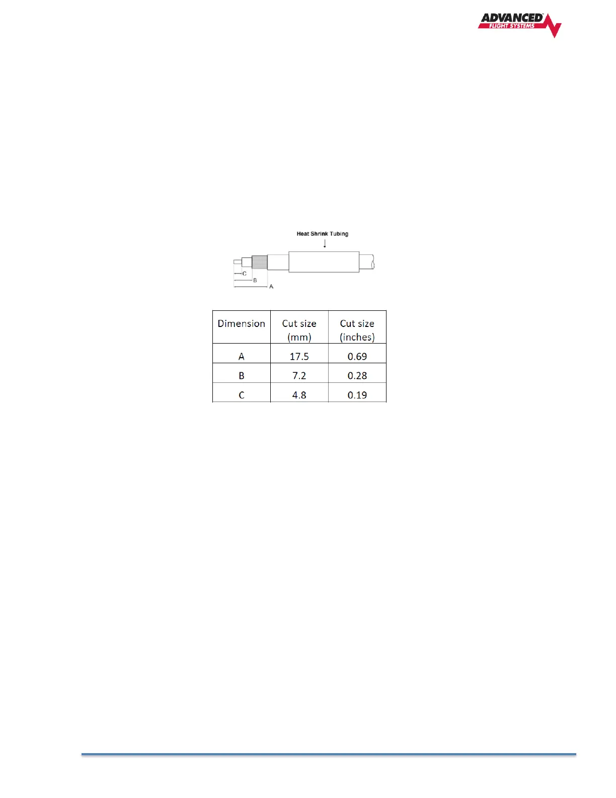
• Strip back the coax cable to the dimensions in the table, as shown in the diagram below. Slide
25 mm (1 inch) of heat shrink tubing over the cable.
• Slide the outer crimp sleeve over the cable – it must go on before securing the center contact.
Crimp the center contact to the cable.
• Insert the cable into the connector – the center contact should click into place in the body, the
inner shield should be inside the body of the connector and the outer shield should be outside
the body.
• Crimp the outer sleeve over the shield.
Slide heat shrink tubing forward (flush to connector) and heat to shrink the tubing.
AF-ADSB -Related AF-5000 Display Settings
Serial Port Setup
Before the ADS-B STATUS menu can be accessed, the AF-ADSB needs to be set up as a serial device on
the AF-5000 display. To accomplish this:
Go to CALIBRATION MENU > SET > CAL > ADMIN Settings
• Navigate to the serial port that you physically connected the AF-ADSB module to in the
previous steps.
• Select 71412 AF-ADSB. Press SAVE.
• Exit SETUP.