Lesson 2 – TIA Setup
484
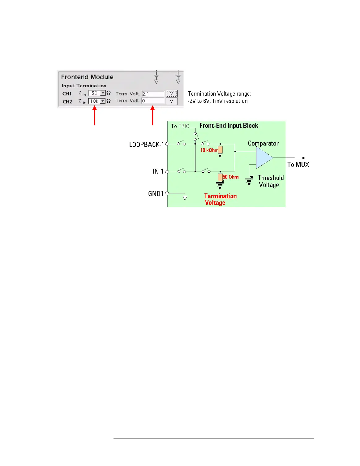
Specifying the Input Termination
NOTE
You can specify a termination voltage when Zin = 10kOhm is selected,
but this voltage will be ignored because the 10kOhm termination is
always connected to ground.
NOTE Naming of the TIA input channels: There are three input channels to each
TIA core. Two channels that carry the signals to be measured, and one
external trigger channel.
In general, the two signal channels are called Channel 1 and Channel 2.
On the Hardware Settings page, the channels are abbreviated to CH1 and
CH2 in the Front-End Module parameter section.
Once the routing has been defined, the two input pins of the front-end
module that are routed to the TIA as Channel 1 and Channel 2 get displayed
in the fields CH IN1 and CH IN2.
When defining the measurement and arming parameters for the TIA,
Channel 1 is referred to as START and Channel 2 is referred to as STOP,
because for dual channel measurements, like propagation delay, the
measurement start is triggered by an edge of Channel 1, and the stop by an
edge of Channel 2.
The external trigger channel is named PE in the Hardware Settings page.
Signal Conditioning
The front-end module performs signal conditioning of the incoming
signals to provide the TIA instruments with two-level signals (high
and low) by comparing with the specified threshold voltage for
 Loading...


