Lesson 1 – Analog Modules
93
In addition to the single-ended/differential input routes, the DC
route is available at any one pin (A+, B+, C+, or D+) in the two
sampler cores. (For the 3GHz Sampler, the loopback route is not
available.)
Each DC route in the SPB has a 1 kohm resistance unlike other
analog modules, in order to provide a wide bandwidth for the
single-ended/differential input routes (by minimizing a reflection
on the stub). The 1 kohm resistance accuracy is approximately
±1%. When you measure or force a voltage using a DC route of the
3GHz Sampler, you need to compensate the voltage drop caused by
this 1 kohm resistance if it is not negligible (the system does not
perform this compensation).
All routing is switched by the input multiplexer.
The sample-and-hold amplifier (S/H amplifier) periodically samples
the high speed input signal and holds it until the analog-to-digital
converter converts it into digital data.
For other components in the sampler (input amplifier, ADC, timing
generator, sequencer, waveform memory, and SYNC_DATA pin),
see the description in “High Resolution / High Speed Digitizer” on
page 79. The timing generator feeds the conversion clock to the
ADC and S/H amplifier in the sampler.
NOTE When you use two sampler cores simultaneously, the sequence
program is shared between the two sampler cores, and the sampling
period, start timing, and stop timing of measurement is the same for
both sampler cores, because the sequencer, timing generator, and
trigger input pin are shared. You can use one sampler core only, or
two sampler cores simultaneously by setting the input multiplexer
accordingly.
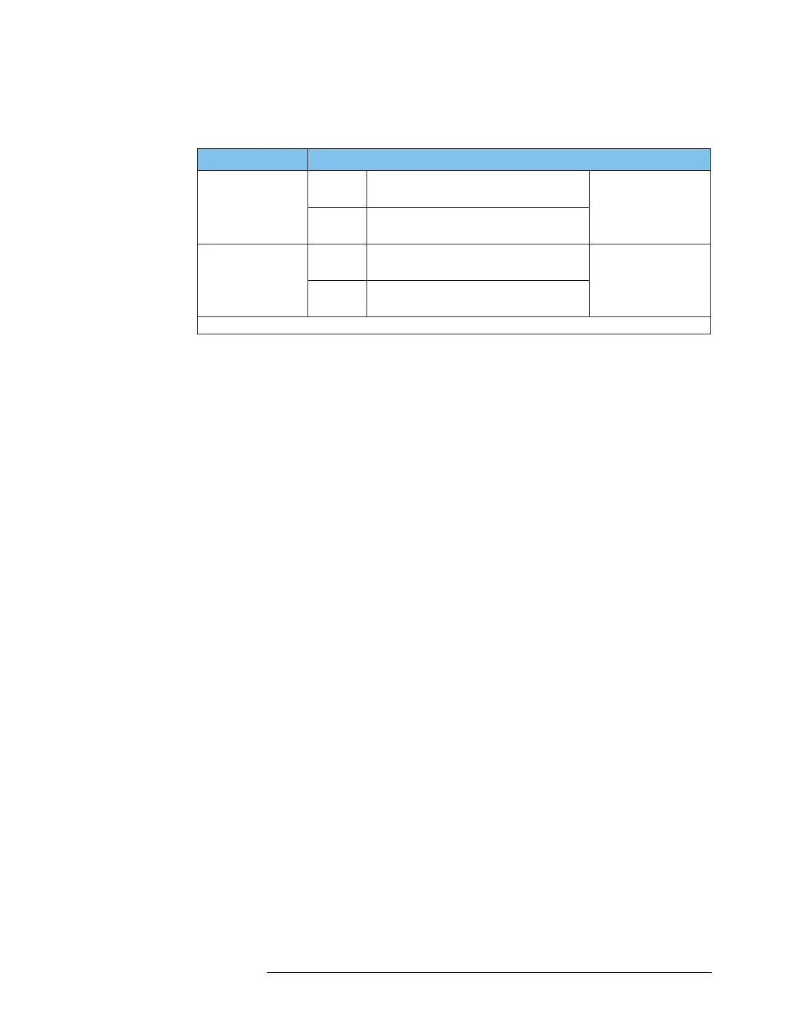
Input Possible Input Pin in Input Route of SPB
Single-ended input
In core 1 1 input only of 2 inputs:
A+ or B+
4 inputs per module.
2 single-ended inputs
simultaneously by us-
ing core 1 and core 2
In core 2 1 input only of 2 inputs:
C+ or D+
Differential input
In core 1 1 input:
A+&B+ pair (B+ is the negative input)
2 inputs per module.
2 differential inputs
simultaneously by us-
ing core 1 and core 2
In core 2 1 input:
C+&D+ pair (D+ is the negative input)
One single-ended input in a core and one differential input in the other core can also be made simultaneously.

 Loading...


