Configuring MVRP MVRP Overview
OmniSwitch AOS Release 8 Network Configuration Guide December 2017 page 12-5
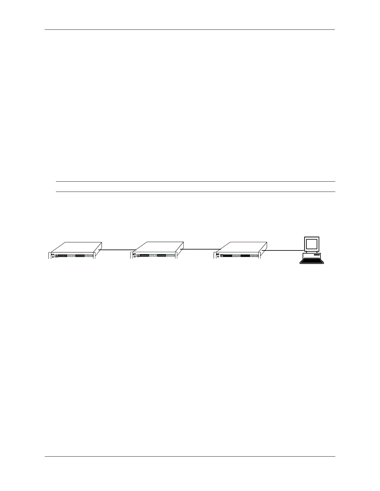
Switch A has 3 VLANs configured as static VLANs (10, 20, and 30). Other switches on the same network
learn these 3 VLANs as dynamic VLANs. Also, the end station connected on port 5 is statically
configured for VLAN 50. Port 1 on Switch A is manually configured for VLANs 10, 20, and 30. All the
ports are in the same Spanning tree instance and are in forwarding state. Hence, as the
Initial Configuration
of MVRP
diagram shows,
1 Port 1 on Switch A advertises VLAN IDs (VIDs) 10, 20, and 30.
2 Port 2 on Switch B receives the advertisements. VLANs 10, 20, and 30 are created as VLANs on this
Switch B and Port 2 become a member of VLANs 10, 20, and 30.
3 Port 3 on Switch B is triggered to advertise VLANs 10, 20, and 30, but does not become a member of
these VLANs.
4 Port 4 on Switch C receives the advertisements. VLANs 10, 20, and 30 are created as VLANs on
Switch C and Port 4 become a member of VLANs 10, 20, and 30.
5 Port 5 advertises VLANs 10, 20, and 30, but this port is not a member of these VLANs.
The configuration sequence of advertisements and registration of VLANs results in the following
configuration.
Dynamic Learning of VLANs 10, 20, and 30
Here, the end station advertises itself as a member of VLAN 50. As the Dynamic Learning of VLANs 10,
20, and 30
diagram shows,
1 Port 5 receives the advertisement and Switch C creates VLAN 50 as a dynamic VLAN. Port 5 of
Switch C becomes a member of VLAN 50.
2 Port 4 advertises VLAN 50, but is not a member of VLAN 50.
3 Port 3 of Switch B receives the advertisement, Switch B creates the dynamic VLAN 50, and Port 3
becomes a member of VLAN 50.
4 Port 2 advertises VLAN 50, but is not a member of this VLAN.
5 Port 1 on Switch A receives the advertisement, creates dynamic VLAN 50. Port 1 becomes a member
of VLAN 50.
The resulting configuration is depicted as follows:
Note. Default VLAN (VLAN 1) exists on all switches, but it is not considered here.
Switch A
Switch C
Switch B
End Station
Static VLAN: 10, 20, 30
Dynamic VLAN
Static VLAN
Dynamic VLAN: 10, 20, 30
1
2
3
4
5
Static VLAN
Dynamic VLAN: 10, 20, 30
Static VLAN 50
 Loading...