S331L UG PN: 10580-00321 Rev. M 3-33
Cable and Antenna Measurements 3-6 Measurement Setup
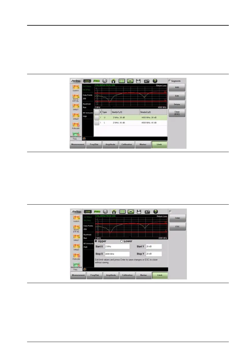
When editing a segmented limit line, a table is displayed with each
segment in a separate row (Figure 3-24). The type is displayed as U or
L. The Start and Stop settings are displayed as Start(x1,y1) and
Stop(x2,y2). In a Return Loss measurement, for example, the x-axis is
in units of frequency, and the y-axis is in units of dB.
When adding or editing a segmented limit line, a dialog box
(Figure 3-25) provides setting choices. You can choose Upper or Lower,
then enter the x-axis and y-axis values for the segment Start and Stop.
Differing y-axis values result in a sloping line segment.
Figure 3-24. Table of Limit Lines (or Segments)
Figure 3-25. Segment Editing Dialog Box