Sheet # 692/1u – Electric connectors (F610)
Version 1.04a User guide ATEQ 6th series Page 2/7
3. ELECTRIC CONNECTORS
3.1. SUPPLY THE DEVICE WITH 24 V DC
Two means are available to supply the device following its configuration.
3.1.1. Supply the device with 24 V DC - 2A on the M12 connector
Plus the fitted power supply to the dedicated M12 Connector.
¾ Pin 2 : + 24 V DC.
¾ Pin 4 : ground 0 V.
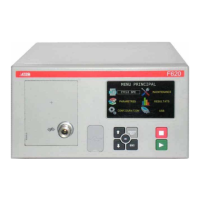
3.1.2. Supply the device with 24 V DC - 2A on the relay board
Connect by using the following mean:
¾ 24 V DC on the pins 2 or 4.
¾ 0 V on the pin 16.
See the paragraph 4.2. "Connector I/O all or nothing".
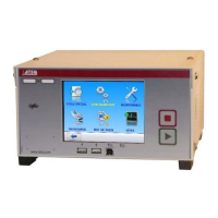
3.2. RS232 C
ONNECTOR PRINTER /MODBUS OR PROFIBUS
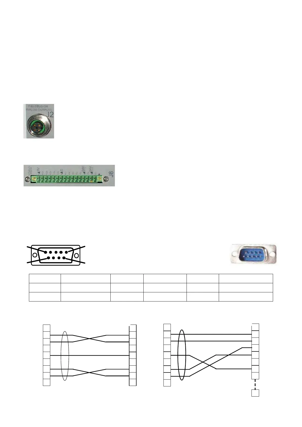
3.2.1. Connector in RS232 mode
1
5
9
6
RS232: SubD 9 points male connector. To plug
a printer, a bar code reader, a PC, a save
module.
Pin 1 Not used Pin 4 Not used Pin 7 RTS request to send
Pin 2 RXD data input Pin 5 Earth/Ground Pin 8 CTS clear to send
Pin 3 TXD data output Pin 6 Not used Pin 9 Not used
3.2.1. 1) Examples of RS232 cables
1
2
3
4
5
6
7
8
9
1
2
3
4
5
6
7
8
9
ATEQ
Use
9 pin SubD
connector
9 pin SubD
connector
RX
TX
GND
RTS
CTS
RX
T
X
GND
RTS
CTS
1
2
3
4
5
6
7
8
9
1
2
3
4
5
6
7
8
TEQ
User
25
9 pin SubD
connector
25 pin SubD
connector
RX
TX
GND
RTS
CTS
RX
T
X
GND
RTS
CTS
 Loading...