Sheet # 697u – CAN Status
Version 1.04a User guide ATEQ 6th series Page 1/1
CAN STATUS
This is to check the communication between the various built in components through the CAN
network (Controller Area Network).
If the network has a defect, restart the device. If the issue persists, contact the ATEQ After
Sales Service.
1. PROCEDURE
From the "SERVICE" menu, select the
"CAN STATUS" menu by using the
arrows and press on
.
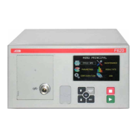
/#+05'48+%'
RESET PARA : No
Ź CAN STATUS
I/O STATE
VALVE COUNTER
DEVICE INFOS
SERVICE CYCLE : No
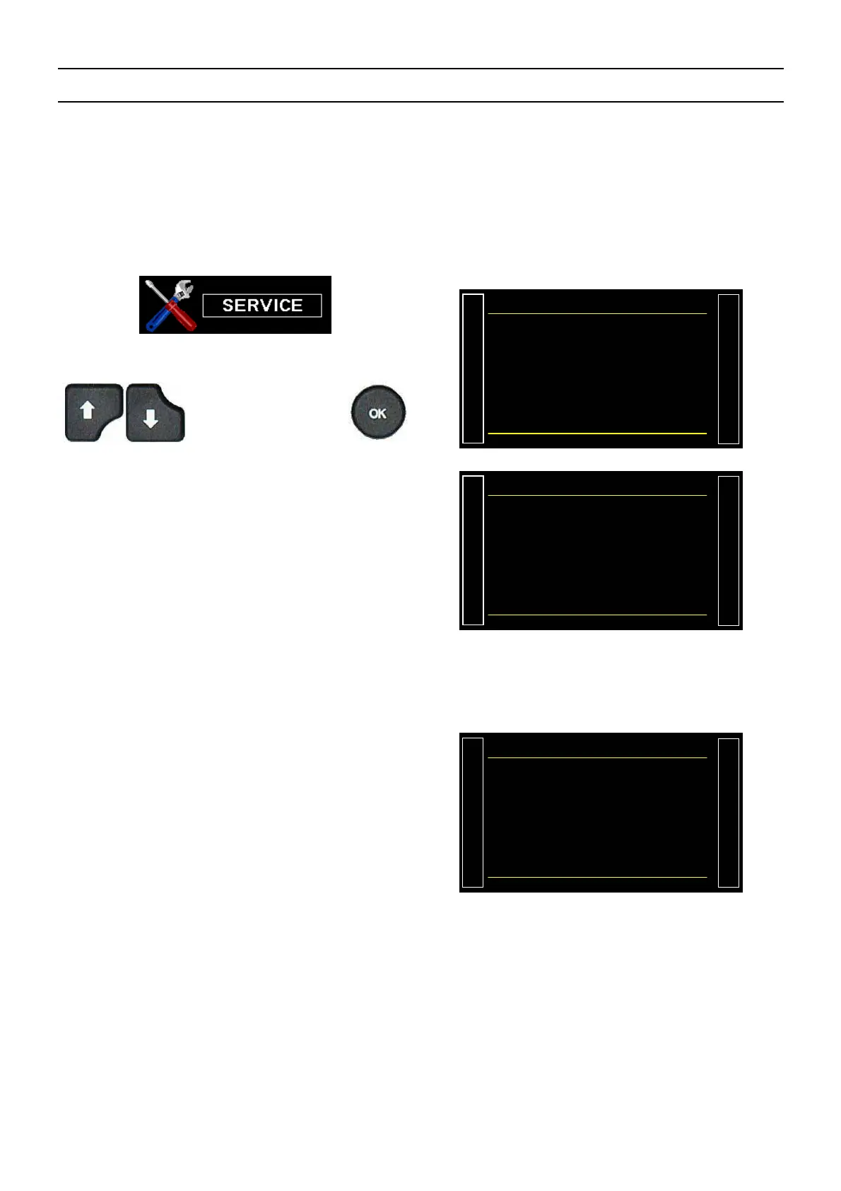
Each built in component may be displayed
with "OK".
If the component if followed with "-------" is not
built in the device.
#+05'48+%#056#67
Ź SENSOR : OK
I/O : OK
VALVE C. : OK
I/O (2) : --------
VALVE C.(2) : --------
SENSOR ERROR : 0
I/O ERROR : 0
VALVE C. ERROR : 0
If one or several board is not detected in the
network, a communication error message is
triggered.
See sheet # 684 "Error messages".
Each component must be displayed: "OK".
If the component if followed by "-------" it's
because it's not installed in the device.
The three displayed counters: "Sensor Error",
"I/O error" et "Valve C. error" are
incremented when communications errors are
detected.
For best functioning, these counters must be
stay on 0.
Note: the counters are reset at each device
power of.
Com. Error
SENSOR BOARD
 Loading...