Sheet # 692/7u – Electric connectors (F670)
Version 1.04a User guide ATEQ 6th series Page 4/7
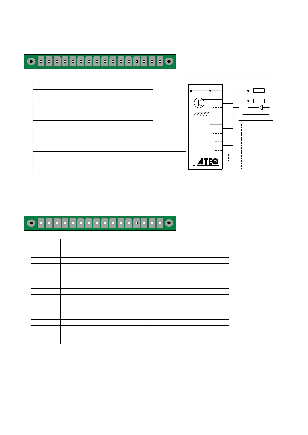
2.5. CONNECTOR CODES 6OUTPUT /6 INPUTS (OPTION)
12345678910111213141516
Output / inputs codes.
Pin 1 COMMUN (Outputs 1, 2, 3) + 24 V DC
Pin 2 Output n°1, open collector
Pin 3 Output n°2, open collector
Pin 4 Output n°3, open collector
Pin 5 COMMON (Outputs 4, 5, 6) + 24 V DC
Pin 6 Output n°4, open collector
Pin 7 Output n°5, open collector
Pin 8 Output n°6, open collector
Output
codes
24V DC
100mA Max
Pin 9 Input 0 (NPN or PNP)*
Pin 10 Input 1 (NPN or PNP)*
Pin 11 Input 2 (NPN or PNP)*
Pin 12 Input 3 (NPN or PNP)*
Inputs
Pin 13 Input 4 (NPN or PNP)*
Pin 14 Ground
Pin 15 Input 5 (NPN or PNP)*
Pin 16 Ground
Analogue
outputs
24 V DC
8
7
6
5
4
3
2
1
0,1 A max
Charge / Load
Obligatory
diode for an
inductive load.
* Inputs NPN or PNP following the strap position on the board.
2.6. J7 CONNECTOR I/O ALL OR NOTHING
12345678910111213141516
Inputs / Outputs All or Nothing.
Pin Standard Mode Compact Mode
1 Input 1 RAZ Input 1 RAZ
2 Common (+ 24 V) Common (+ 24 V)
3 Input 2 START Input 2 START
4 Common (+ 24 V) Common (+ 24 V)
5 Input 3 Program selection Input 3 Program selection
6 Input 4 Program selection Input 4 Program selection
7 Input 5 Program selection Input 5 Program selection
8 Input 6 Program selection Input 6 Program selection
9 Input 7 Program selection Input 7 Program selection
Inputs
(Activation by
24 V DC)
Common
+ 24 V = 0,3 A
maximum
10 Floating common output Floating common output
11 Output 1 Pass part Output 1Pass part cycle 1
12 Output 2 Fail Test part Output 2 Fail part cycle 1 + Alarm
13 Output 3 Fail reference part Output 3 Pass part cycle 2
14 Output 4 Alarm Output 4 Fail part cycle 2 + Alarm
15 Output 5 End of cycle Output 5 End of cycle
16 0 V 0 V
Outputs dry
contacts
60V AC / DC Max
200mA Max
The compact mode is a software function which is activated in the CONFIGURATION/
AUTOMATISM / CHANGE I/O / OUTPUT menu.
 Loading...