116
8331B–AVR–03/12
Atmel AVR XMEGA AU
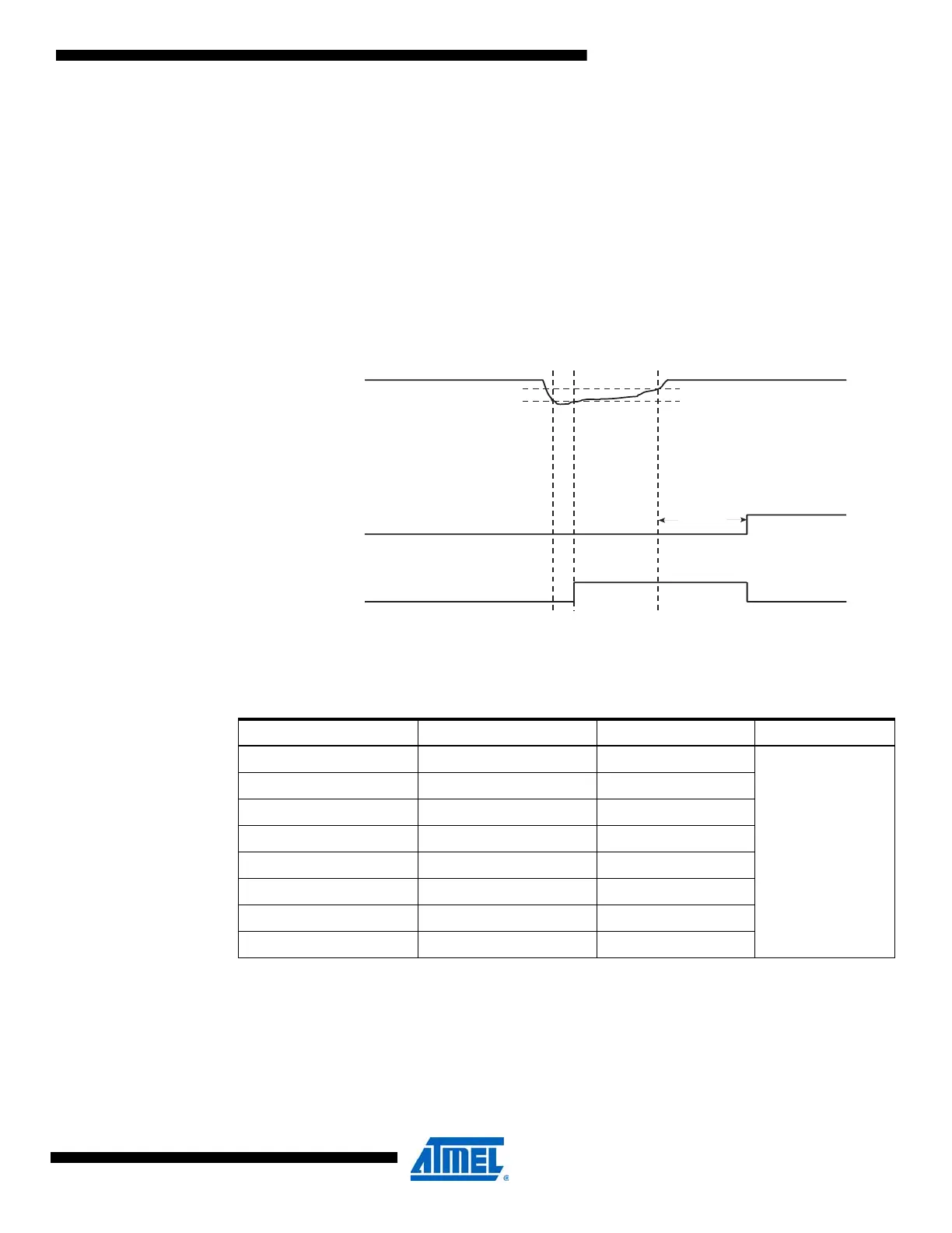
When the BOD is enabled and V
CC
decreases to a value below the trigger level (V
BOT-
in Figure
9-4), the brownout reset is immediately activated.
When V
CC
increases above the trigger level (V
BOT+
in Figure 9-4), the reset counter starts the
MCU after the timeout period, t
TOUT
, has expired.
The trigger level has a hysteresis to ensure spike free brownout detection. The hysteresis on the
detection level should be interpreted as V
BOT+
= V
BOT
+ V
HYST
/2 and V
BOT-
= V
BOT
- V
HYST
/2.
The BOD circuit will detect a drop in V
CC
only if the voltage stays below the trigger level for lon-
ger than t
BOD
.
Figure 9-4. Brownout detection reset.
For BOD characterization data consult the device datasheet. The programmable BODLEVEL
setting is shown in Table 9-2.
Notes: 1. The values are nominal values only. For accurate, actual numbers, consult the device
datasheet.
2. Changing these fuse bits will have no effect until leaving programming mode.
The BOD circuit has three modes of operation:
• Disabled: In this mode, there is no monitoring of the V
CC
level.
Table 9-2. Programmable BODLEVEL setting.
BOD level Fuse BODLEVEL[2:0]
(2)
V
BOT
(1)
Unit
BOD level 0 111 1.6
V
BOD level 1 110 1.8
BOD level 2 101 2.0
BOD level 3 100 2.2
BOD level 4 011 2.4
BOD level 5 010 2.6
BOD level 6 001 2.8
BOD level 7 000 3.0
V
CC
TIME-OUT
INTERNAL
RESET
V
BOT-
V
BOT+
t
TOUT
t
BOD

 Loading...


