162
8331B–AVR–03/12
Atmel AVR XMEGA AU
• Bit 3:2 – EBIADROUT[1:0]: EBI Address Output
The maximum configuration of the external bus interface (EBI) requires up to 32 dedicated pins.
For devices with only 24 EBI pins available, eight additional pins can be enabled and placed on
alternate pin locations in order to get a full 32-pin EBI. The port pins must be configured as out-
put for signals to be available on the pins. These bits are available on devices with only three
ports dedicated for the EBI interface. The selections are valid only if the EBI is configured to
operate in four-port mode.
• Bit 1:0 – EBICSOUT[1:0]: EBI Chip Select Output
These bits decide which port the EBI chip select signals will be output to. The pins must be con-
figured as output pins for signals to be available on the pins. Refer to ”Register Description –
EBI” on page 346 for chip select configuration.
13.14.6 EVCTRL – Event Control register
• Bit 7:3 – Reserved
These bits are unused and reserved for future use. For compatibility with future devices, always
write these bits to zero when this register is written.
• Bit 2:0 – EVOUTSEL[2:0]: Event Channel Output Selection
These bits define which channel from the event system is output to the port pin. Table 13-14 on
page 163 shows the available selections.
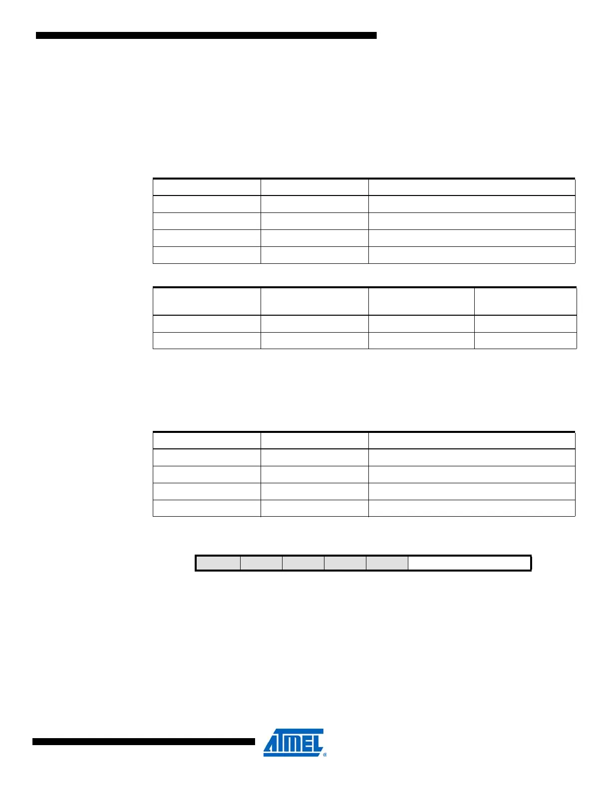
Table 13-11. EBI address output port selection.
EBIADROUT[1:0] Group Configuration Description
00 PF EBI port 3 address output on PORTF pins 0 to 7
01 PE EBI port 3 address output on PORTE pins 0 to 7
10 PFH EBI port 3 address output on PORTF pins 4 to 7
11 PEH EBI port 3 address output on PORTE pins 4 to 7
Table 13-12. EBI address output .
EBIADROUT SDRAM SRAM or SRAM LPC
(with SDRAM on CS3)
SRAM
NOALE or ALE1
00 or 01 4’h0, A[11:8] A[23:16] A[15:8]
10 or 11 A[11:8] [19:16] –
Table 13-13. EBI chip select port selection.
EBICSOUT[1:0] Group Configuration Description
00 PH EBI chip select output to PORTH pin 4 to 7
01 PL EBI chip select output to PORTL pin 4 to 7
10 PF EBI chip select output to PORTF pin 4 to 7
11 PE EBI chip select output to PORTE pin 4 to 7
Bit 7 6543210
+0x06 – – – – – EVOUTSEL[2:0] EVCTRL
Read/Write R R R R R R/W R/W R/W
Initial Value 0 0 0 0 0 0 0 0

 Loading...


