161
8331B–AVR–03/12
Atmel AVR XMEGA AU
Table 13-8 on page 161 shows the possible configurations.
• Bits 3:2 – CLKOUTSEL[1:0] : Clock Output Select
These bits are used to select which of the peripheral clocks will be output to the port pin if CLK-
OUT is configured.
• Bit 1:0 – CLKOUT[1:0]: Clock Output Port
These bits decide which port the peripheral clock will be output to. Pin 7 on the selected port is
the default used. The CLKOUT setting will override the EVOUT setting. Thus, if both are
enabled on the same port pin, the peripheral clock will be visible. The port pin must be config-
ured as output for the clock to be available on the pin.
Table 13-10 on page 161 shows the possible configurations.
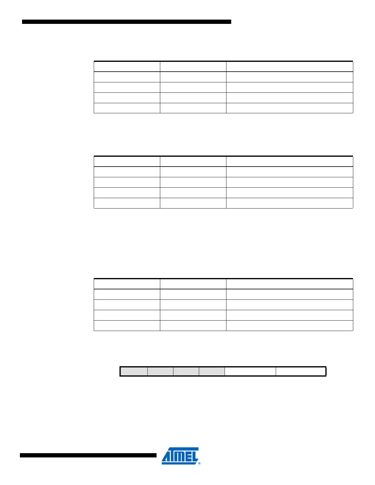
13.14.5 EBIOUT – EBI Output register
• Bit 7:4 – Reserved
These bits are unused and reserved for future use. For compatibility with future devices, always
write these bits to zero when this register is written.
Table 13-8. Event output pin selection.
EVOUT[1:0] Group Configuration Description
00 OFF Event output disabled
01 PC Event channel 0 output on PORTC
10 PD Event channel 0 output on PORTD
11 PE Event channel 0 output on PORTE
Table 13-9. Event output clock selection.
CLKOUTSEL[1:0] Group Configuration Description
00 CLK1X CLK
PER
output to pin
01 CLK2X CLK
PER2
output to pin
10 CLK4X CLK
PER4
output to pin
Table 13-10. Clock output port configurations.
CLKOUT[1:0] Group Configuration Description
00 OFF Clock output disabled
01 PC Clock output on PORTC
10 PD Clock output on PORTD
11 PE Clock output on PORTE
Bit 7 6543210
+0x05 – – – – EBIADROUT[1:0] EBICSOUT[1:0] CLKEVOUT
Read/Write R R R R R/W R/W R/W R/W
Initial Value 0 0 0 0 0 0 0 0

 Loading...


