252
8331B–AVR–03/12
Atmel AVR XMEGA AU
• Bit 5 – BUSERRIE: Bus Error Interrupt Enable
Setting this bit will enable the interrupt for the following three bus error events:
1. Isochronous CRC Error: An interrupt will be generated for the conditions that set the
CRC interrupt flag (CRCIF) in the INTFLAGSACLR/SET register during isochronous
transfers.
2. Underflow: An interrupt will be generated for the conditions that set the undeflow inter-
rupt flag (UNFIF) in the INTFLAGSACLR/SET register.
3. Overflow: An interrupt will be generated for the conditions that set the overflow interrupt
flag (OVFIF) in the INTFLAGSACLR/SET register.
The INTLVL bits must be nonzero for the interrupts to be generated.
• Bit 4 – STALLIE: STALL Interrupt Enable
Setting this bit enables the STALL interrupt for the conditions that set the stall interrupt flag
(STALLIF) in the INTFLAGSACLR/SET register. The INTLVL bits must be nonzero for the inter-
rupts to be generated.
• Bit 3:2 – Reserved
These bits are unused and reserved for future use. For compatibility with future devices, always
write these bits to zero when this register is written.
• Bit 1:0 – INTLVL[1:0]: Interrupt Level
These bits enable the USB interrupts and select the interrupt level, as described in ”Interrupts
and Programmable Multilevel Interrupt Controller” on page 134. In addition, each USB interrupt
source must be separately enabled.
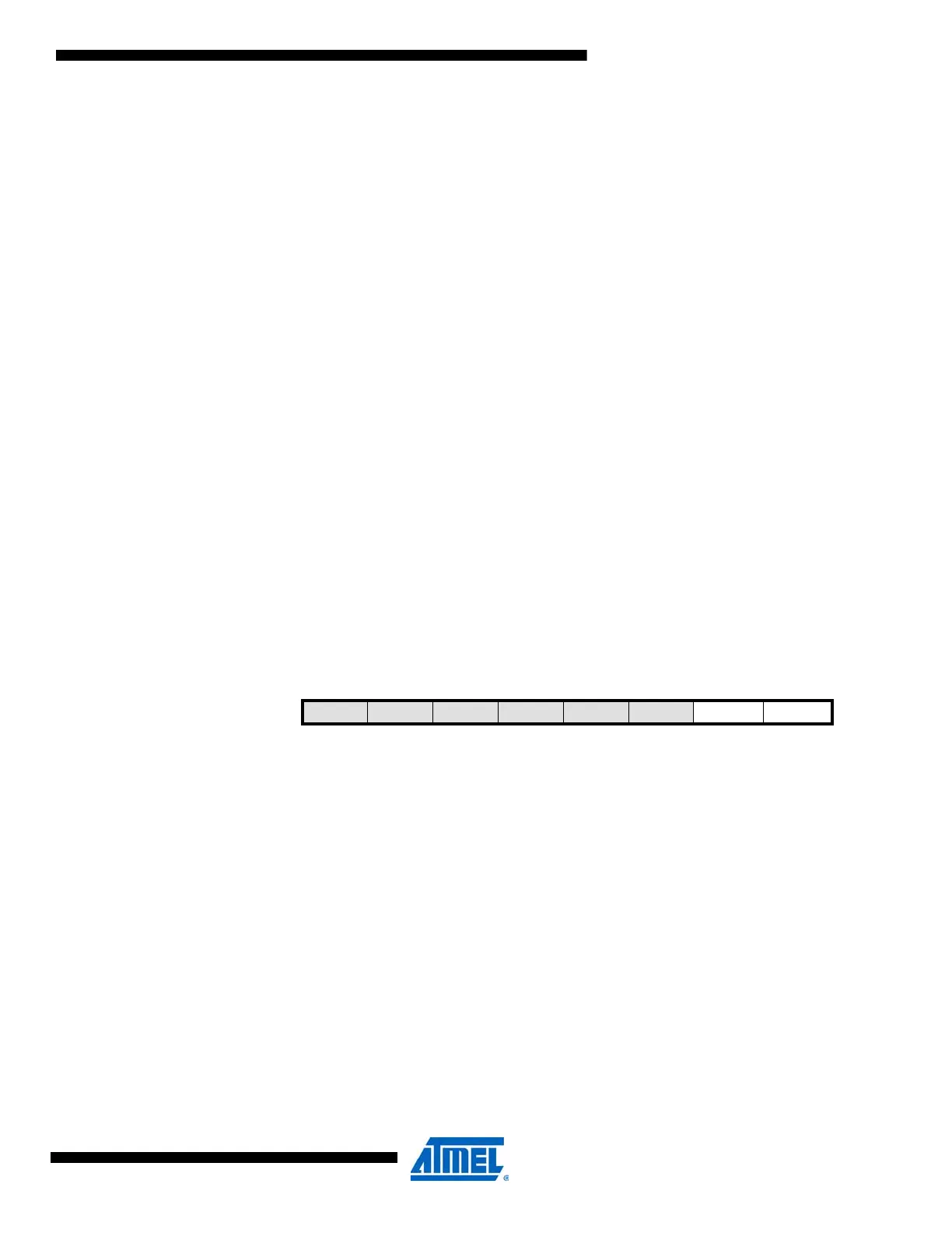
20.13.10 INTCTRLB – Interrupt Control register B
• Bit 7:2 – Reserved
These bits are unused and reserved for future use. For compatibility with future devices, always
write these bits to zero when this register is written.
• Bit 1 – TRNIE: Transaction Complete Interrupt Enable
Setting this bit enables the transaction complete interrupt for IN and OUT transactions. The
INTLVL bits must be nonzero for interrupts to be generated.
• Bit 0 – SETUPIE: SETUP Transaction Complete Interrupt Enable
Setting this bit enables the SETUP Transaction Complete Interrupt for SETUP transactions. The
INTLVL bits must be non-zero for the interrupts to be generated.
20.13.11 INTFLAGSACLR/ INTFLAGSASET – Clear/ Set Interrupt Flag register A
This register is mapped into two I/O memory locations, one for clearing (INTFLAGSACLR) and
one for setting (INTFLAGSASET) the flags. The individual flags can be set by writing a one to
their bit locations in INFLAGSASET, and cleared by writing a one to their bit locations in INT--
Bit 765432 1 0
+0x07 – – – – – – TRNIE SETUPIE INTCTRLB
Read/WriteRRRRRRR/WR/W
Initial Value 0 0 0 0 0 0 0 0

 Loading...


