313
8331B–AVR–03/12
Atmel AVR XMEGA AU
• Bits 5:4 – PMODE[1:0]: Parity Mode
These bits enable and set the type of parity generation according to Table 23-8 on page 313.
When enabled, the transmitter will automatically generate and send the parity of the transmitted
data bits within each frame. The receiver will generate a parity value for the incoming data and
compare it to the PMODE setting, and if a mismatch is detected, the PERR flag in STATUS will
be set.
These bits are unused in master SPI mode operation.
• Bit 3 – SBMODE: Stop Bit Mode
This bit selects the number of stop bits to be inserted by the transmitter according to Table 23-9
on page 313. The receiver ignores this setting.
This bit is unused in master SPI mode operation.
• Bit 2:0 – CHSIZE[2:0]: Character Size
The CHSIZE[2:0] bits set the number of data bits in a frame according to Table 23-10 on page
313. The receiver and transmitter use the same setting.
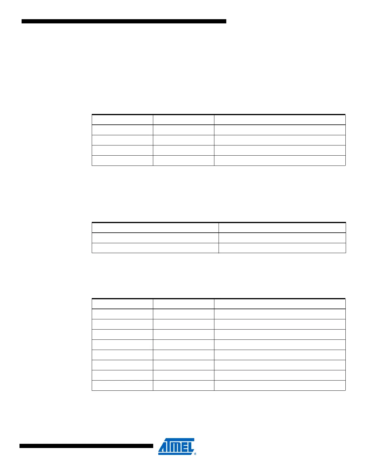
Table 23-8. PMODE bit settings.
PMODE[1:0] Group Configuration Parity Mode
00 DISABLED Disabled
01 Reserved
10 EVEN Enabled, even parity
11 ODD Enabled, odd parity
Table 23-9. SBMODE bit settings.
SBMODE Stop Bit(s)
01
12
Table 23-10. CHSIZE bit settings.
CHSIZE[2:0] Group Configuration Character Size
000 5BIT 5-bit
001 6BIT 6-bit
010 7BIT 7-bit
011 8BIT 8-bit
100 Reserved
101 Reserved
110 Reserved
111 9BIT 9-bit

 Loading...


