381
8331B–AVR–03/12
Atmel AVR XMEGA AU
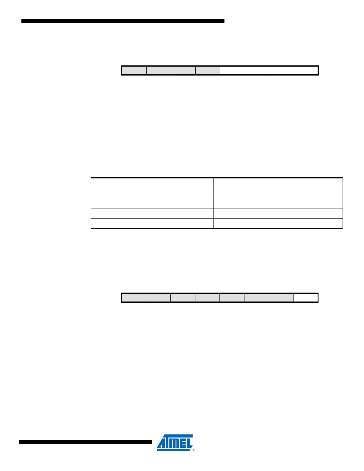
28.17.3 INTCTRL – Channel Interrupt Control registers
• Bits 7:4 – Reserved
These bits are unused and reserved for future use. For compatibility with future devices, always
write these bits to zero when this register is written.
• Bit 3:2 – INTMODE: Interrupt Mode
These bits select the interrupt mode for the channel according to Table 28-18.
• Bits 1:0 – INTLVL[1:0]: Interrupt Priority Level and Enable
These bits enable the ADC channel interrupt and select the interrupt level, as described in ”Inter-
rupts and Programmable Multilevel Interrupt Controller” on page 134. The enabled interrupt will
be triggered for conditions when the IF bit in the INTFLAGS register is set.
28.17.4 INTFLAGS – ADC Channel Interrupt Flag registers
• Bit 7:1 – Reserved
These bits are unused and reserved for future use. For compatibility with future devices, always
write these bits to zero when this register is written.
• Bit 0 – IF: Channel Interrupt Flag
The interrupt flag is set when the ADC conversion is complete. If the channel is configured for
compare mode, the flag will be set if the compare condition is met. IF is automatically cleared
when the ADC channel interrupt vector is executed. The bit can also be cleared by writing a one
to the bit location.
28.17.5 RESH – Channel n Result register High
For all result registers and with any ADC result resolution, a signed number is represented in 2’s
complement form, and the msb represents the sign bit.
Bit 76543210
+0x02 – – – – INTMODE[1:0} INTLVL[1:0] INTCTRL
Read/Write R R R R R/W R/W R/W R/W
Initial Value 0 0 0 0 0 0 0 0
Table 28-18. ADC interrupt mode.
INTMODE[1:0] Group Configuration Interrupt Mode
00 COMPLETE Conversion complete
01 BELOW Compare result below threshold
10 Reserved
11 ABOVE Compare result above threshold
Bit 76543210
+0x03 – – – – – – – IF INTFLAGS
Read/WriteRRRRRRRR/W
Initial Value 0 0 0 0 0 0 0 0

 Loading...


