380
8331B–AVR–03/12
Atmel AVR XMEGA AU
Depending on the device pin count and feature configuration, the actual number of analog input
pins may be less than 16. Refer to the device datasheet and pin-out description for details.
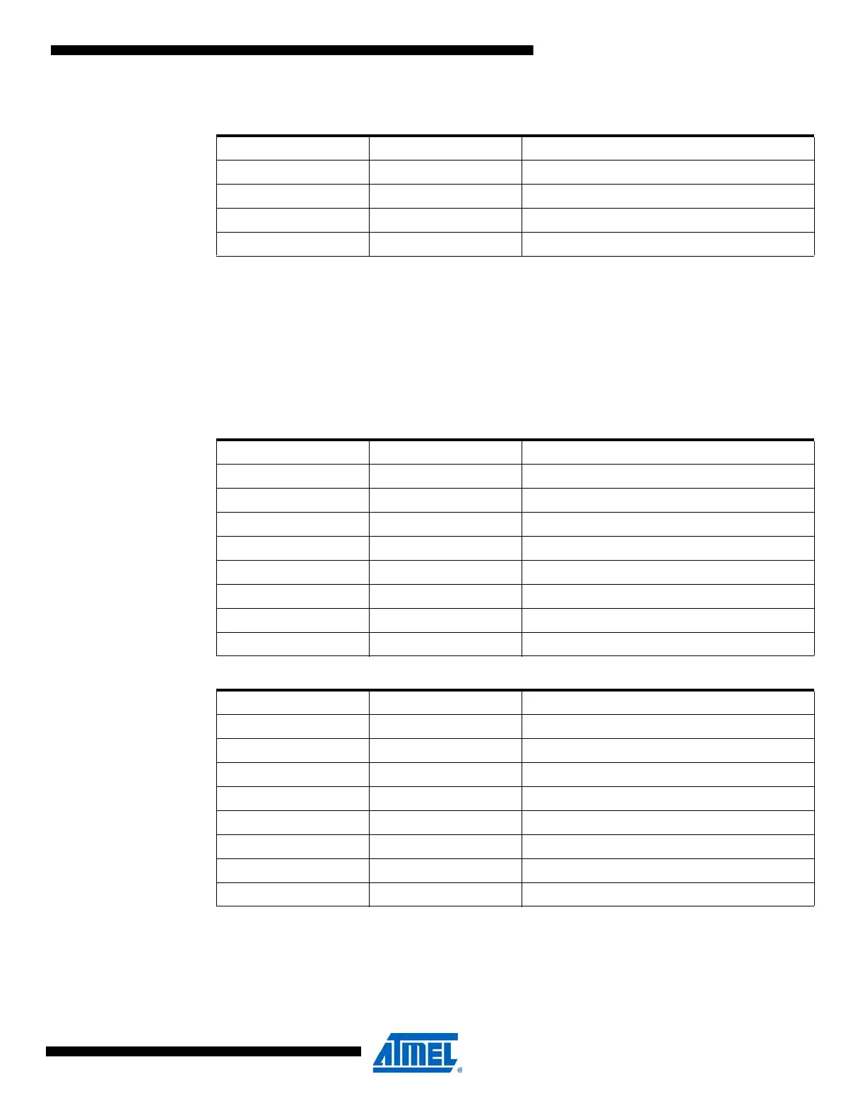
• Bit 2:0 – MUXNEG[2:0]: MUX Selection on Negative ADC Input
These bits define the MUX selection for the negative ADC input when differential measurements
are done. For internal or single-ended measurements, these bits are not used.
Table 28-16 on page 380 andTable 28-17 on page 380 show the possible input sections.
0100 PIN4 ADC4 pin
0101 PIN5 ADC5 pin
0110 PIN6 ADC6 pin
0111 PIN7 ADC7 pin
1XXX Reserved
Table 28-16. ADC MUXNEG configuration, INPUTMODE[1:0] = 10, differential without gain.
MUXNEG[2:0] Group Configuration Analog Input
000 PIN0 ADC0 pin
001 PIN1 ADC1 pin
010 PIN2 ADC2 pin
011 PIN3 ADC3 pin
100 - Reserved
101 GND PAD ground
110 - Reserved
111 INTGND Internal ground
Table 28-17. ADC MUXNEG configuration, INPUTMODE[1:0] = 11, differential with gain.
MUXNEG[2:0] Group Configuration Analog Input
000 PIN4 ADC4 pin
001 PIN5 ADC5 pin
010 PIN6 ADC6 pin
011 PIN7 ADC7 pin
100 INTGND Internal ground
101 - Reserved
110 - Reserved
111 GND PAD ground
Table 28-15. ADC MUXPOS configuration when INPUTMODE[1:0] = 11 (differential with gain)
is used. (Continued)

 Loading...


