379
8331B–AVR–03/12
Atmel AVR XMEGA AU
• Bit 6:3 – MUXPOS[3:0]: MUX Selection on Positive ADC Input
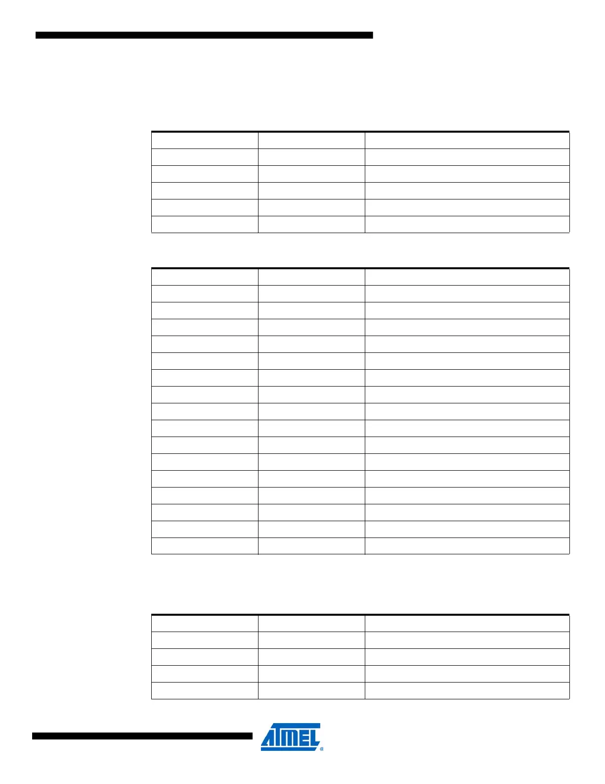
These bits define the MUX selection for the positive ADC input. Table 28-13 on page 379 and
Table 28-14 on page 379 show the possible input selection for the different input modes.
Table 28-13. ADC MUXPOS configuration when INPUTMODE[1:0] = 00 (internal) is used.
MUXPOS[3:0] Group Configuration Description
0000 TEMP Temperature reference
0001 BANDGAP Bandgap voltage
0010 SCALEDVCC 1/10 scaled V
CC
0011 DAC DAC output
0100-1111 Reserved
Table 28-14. ADC MUXPOS configuration when INPUTMODE[1:0] = 01 (single-ended) or
INPUTMODE[1:0] = 10 (differential) is used.
MUXPOS[3:0] Group Configuration Description
0000 PIN0 ADC0 pin
0001 PIN1 ADC1 pin
0010 PIN2 ADC2 pin
0011 PIN3 ADC3 pin
0100 PIN4 ADC4 pin
0101 PIN5 ADC5 pin
0110 PIN6 ADC6 pin
0111 PIN7 ADC7 pin
1000 PIN8 ADC8 pin
1001 PIN9 ADC9 pin
1010 PIN10 ADC10 pin
1011 PIN11 ADC11 pin
1100 PIN12 ADC12 pin
1101 PIN13 ADC13 pin
1110 PIN14 ADC14 pin
1111 PIN15 ADC15 pin
Table 28-15. ADC MUXPOS configuration when INPUTMODE[1:0] = 11 (differential with gain)
is used.
MUXPOS[3:0] Group Configuration Description
0000 PIN0 ADC0 pin
0001 PIN1 ADC1 pin
0010 PIN2 ADC2 pin
0011 PIN3 ADC3 pin

 Loading...


