378
8331B–AVR–03/12
Atmel AVR XMEGA AU
See Table 28-8 on page 373. Gain is valid only with certain MUX settings. See ”MUXCTRL –
ADC Channel MUX Control registers” on page 378.
• Bit 1:0 – INPUTMODE[1:0]: Channel Input Mode
These bits define the channel mode. Changing input mode will corrupt any data in the pipeline.
28.17.2 MUXCTRL – ADC Channel MUX Control registers
The MUXCTRL register defines the input source for the channel.
• Bit 7 – Reserved
This bit is unused and reserved for future use. For compatibility with future devices, always write
this bit to zero when this register is written.
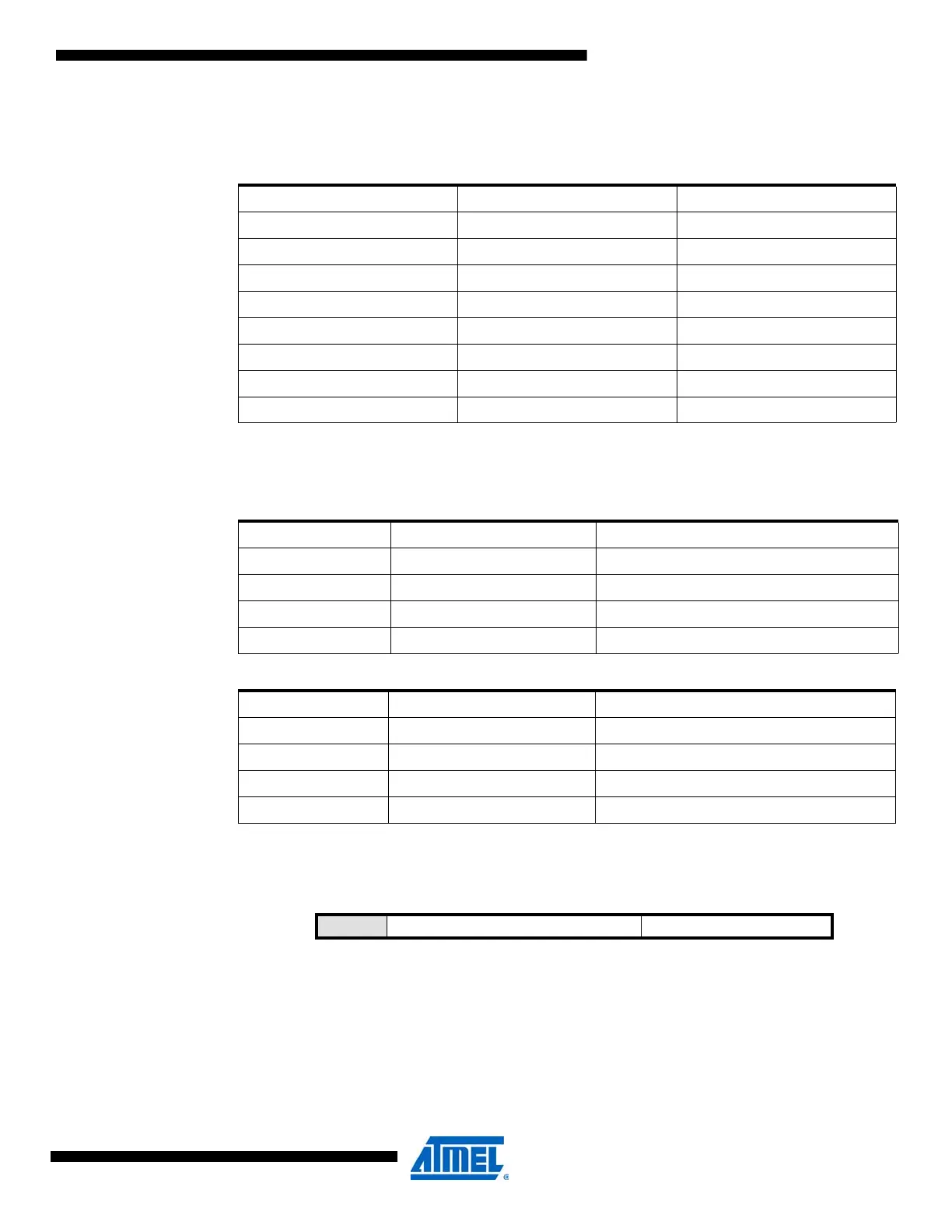
Table 28-10. ADC gain factor.
GAIN[2:0] Group Configuration Gain Factor
000 1X 1x
001 2X 2x
010 4X 4x
011 8X 8x
100 16X 16x
101 32X 32x
110 64X 64x
111 DIV2 ½x
Table 28-11. Channel input modes, CONVMODE=0 (unsigned mode).
INPUTMODE[1:0] Group Configuration Description
00 INTERNAL Internal positive input signal
01 SINGLEENDED Single-ended positive input signal
10 Reserved
11 Reserved
Table 28-12. Channel input modes, CONVMODE=1 (signed mode).
INPUTMODE[1:0] Group Configuration Description
00 INTERNAL Internal positive input signal
01 SINGLEENDED Single-ended positive input signal
10 DIFF Differential input signal
11 DIFFWGAIN Differential input signal with gain
Bit 7 6543210
+0x01 – MUXPOS[3:0] MUXNEG[2:0] MUXCTRL
Read/Write R R/W R/W R/W R/W R R/W R/W
Initial Value 0 0 0 0 0 0 0 0
 Loading...


