Page 4–8
DURApulse GS4 AC Drive User Manual – 1st Ed, Rev A - 10/20/2017
Chapter 4: AC Drive Parameters
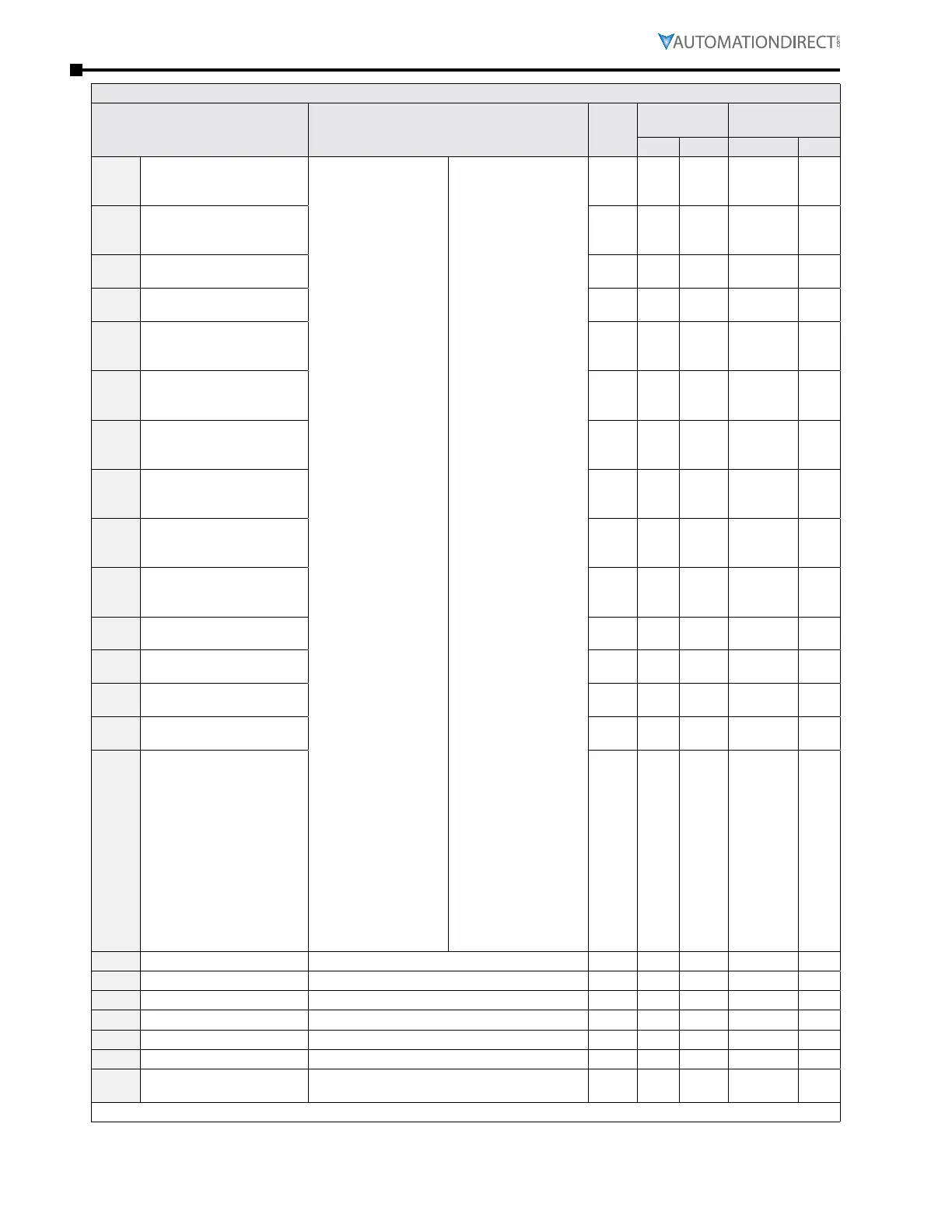
GS4 Parameters Summary – Digital Parameters (P3.xx) – (continued)
Parameter Range
Run
Read/
Write
Modbus
Address
Settings
Hex Dec Default User
P3.17
Multi-Function Output
Terminal 1
(Relay 1 or PLC Y0)
0: no function
1: AC Drive Running
2: At Frequency
Setpoint
3: At Speed 1 (P3�32)
4: At Speed 2 (P3�34)
5: At Zero Speed
Including Drive
Running
6: At Zero Speed
Drive not Running
7: Over Torque Level 1
8: Over Torque Level 2
9: Drive Ready
10: Low Voltage
warning (Lv)
11: Error indication
(All faults, Except
for Lv Stop)
12: Brake Release
Function (P3�51)
13: Over-temp
Warning
14: Dynamic Braking
Output
15: PID deviation error
16: Over Slip (oSL)
17: Middle Count
Value Attained
(P3�45)
18: Final Count Value
Attained (P3�44)
19: Base Block
Indication
20: Warning Output
21: Overvoltage Alarm
22: Oc Stall Alarm
23: Ov Stall Alarm
24: External Control
Mode
25: Forward
Command
26: Reverse Command
27: Above Current
Output (≥ P3.52)
28: Below Current
Output (< P3�52)
29: Wye Connected
Command
30: Delta Connected
Command
31: Zero Speed at
Drive Running
32: Zero Speed
including Drive
Stop
33: Fault Option 1
(P11�00)
34: Fault Option 2
(P11�01)
35: Fault Option 3
(P11�02)
36: Fault Option 4
(P11�03)
37: At Speed (Setpoint
include 0Hz)
38: reserved
39: Under Ampere
(Low Current)
40: UVW Motor
Contactor Enable
41: DEB active
42: Brake Released at
Stop
43: RS485 Digital
Output
44: Comm Card Digital
Output
45: Fire Mode
Indication
46: Fire Bypass
Indication
47: Motor #1 Selected
48: Motor #2 Selected
49: Motor #3 Selected
50: Motor #4 Selected
51: Motor #5 Selected
52: Motor #6 Selected
53: Motor #7 Selected
54: Motor #8 Selected
55: Mtr1/Mtr2
Nameplate
Parameters Select
56: Safety N�O� STO A
57: Safety N�C� STO B
58: Above Frequency
Output (≥ P3.53)
59: Below Frequency
Output (< P3�53)
♦R/W 0311 40786 11
P3.18
Multi-Function Output
Terminal 2
(Relay 2 or PLC Y1)
♦R/W 0312 40787 1
P3.19
Multi-Function Output
Terminal 3 (DO1 or PLC Y3)
♦R/W 0313 40788 0
P3.20
Multi-Function Output
Terminal 4 (DO2 or PLC Y4)
♦R/W 0314 40789 0
P3.21
Multi-Function Output
Terminal 5 (option card
DO10 or RO10, or PLC Y5)
♦R/W 0315 40790 0
P3.22
Multi-Function Output
Terminal 6 (option card
DO11 or RO11, or PLC Y6)
♦R/W 0316 40791 0
P3.23
Multi-Function Output
Terminal 7 (option card
RO12 or PLC Y7)
♦R/W 0317 40792 0
P3.24
Multi-Function Output
Terminal 8 (option card
RO13 or PLC Y10)
♦R/W 0318 40793 0
P3.25
Multi-Function Output
Terminal 9 (option card
RO14 or PLC Y11)
♦R/W 0319 40794 0
P3.26
Multi-Function Output
Terminal 10 (option card
RO15 or PLC Y12)
♦R/W 031A 40795 0
P3.27
Multi-Function Virtual
Output 11 (DO16, PLC Y13)
♦R/W 031B 40796 0
P3.28
Multi-Function Virtual
Output 12 (DO17, PLC Y14)
♦R/W 031C 40797 0
P3.29
Multi-Function Virtual
Output 13 (DO18, PLC Y15)
♦R/W 031D 40798 0
P3.30
Multi-Function Virtual
Output 14 (DO19, PLC Y16)
♦R/W 031E 40799 0
P3.31
Multi-Function Virtual
Output 15 (DO20, PLC Y17)
♦R/W 031F 40800 0
P3.32
Desired Frequency 1 0�00~600�00 Hz ♦R/W 0320 40801 60�00
P3.33
Desired Frequency 1 Width 0�00~600�00 Hz ♦R/W 0321 40802 2�00
P3.34
Desired Frequency 2 0�00~600�00 Hz ♦R/W 0322 40803 60�00
P3.35
Desired Frequency 2 Width 0�00~600�00 Hz ♦R/W 0323 40804 2�00
P3.36
PID Deviation Level 1�0~50�0% ♦R/W 0324 40805 10�0
P3.37
PID Deviation Time 0�1~300�0 sec ♦R/W 0325 40806 5�0
P3.38
Frequency Output (FO)
Scaling Factor
1~166 ♦R/W 0326 40807 1
(table continued next page)

 Loading...
