Chapter 4: AC Drive Parameters
Page 4–17
DURApulse GS4 AC Drive User Manual – 1st Ed, Rev A - 10/20/2017
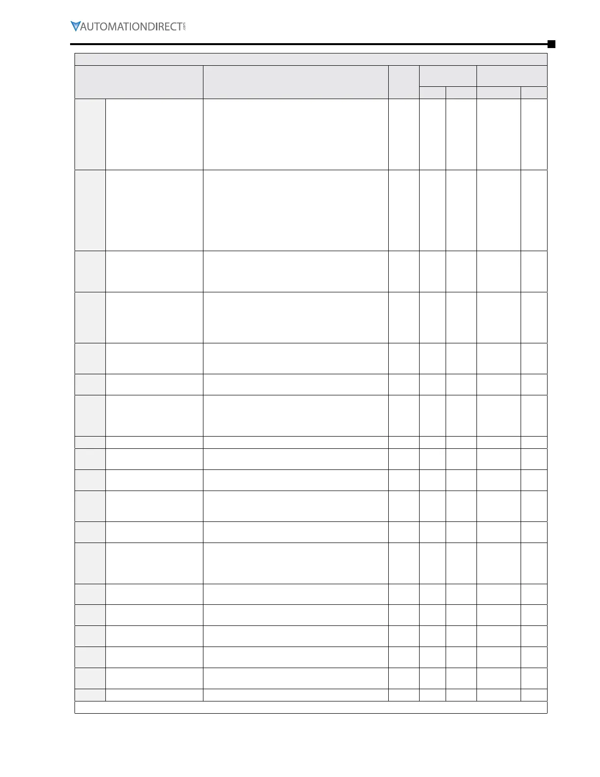
GS4 Parameters Summary – Protection Parameters (P6.xx) – (continued)
Parameter Range
Run
Read/
Write
Modbus
Address
Settings
Hex Dec Default User
P6.33
Drive Derating Method
Note: there are
iNterdepeNdeNcies betweeN
p2.10, p6.00/p6.02,
p6.33, p6.34. refer to
parameter details wheN
settiNg these parameters.
0: Constant rated current
1: Constant carrier frequency
2: Constant rated current
(with higher current limit)
R/W 0621 41570 0
P6.34
Variable/Constant
Torque Duty Selection
Note: there are
iNterdepeNdeNcies betweeN
p2.10, p6.00/p6.02,
p6.33, p6.34. refer to
parameter details wheN
settiNg these parameters.
0: VT, 3-phase input
1: CT, 3-phase input
2: CT, 230V 1-phase input
♦R/W 0622 41571 0
P6.35
Low Voltage Level
230V Frame <E: 150�0~220�0 VDC
230V Frame ≥E: 190.0~220.0 VDC
460V Frame <E: 300�0~440�0 VDC
460V Frame ≥E: 380.0~440.0 VDC
♦R/W 0623 41572
180�0
200�0
360�0
400�0
P6.36
OC Stall Preventation
Accel/Decel Time
Selection at Normal
Speed
1: Follow the 1st Accel/Decel Time
2: Follow the 2nd Accel/Decel Time
3: Follow the 3rd Accel/Decel Time
4: Follow the 4th Accel/Decel Time
5: Auto Accel/Decel
♦R/W 0624 41573 0
P6.37
OC Stall Preventation
Limit for operation over
Rated Speed
0~100% ♦R/W 0625 41574 50
P6.38
Torque Limit (Current
Limit)
0~200% ♦R/W 0626 41575 150
P6.39
PTC/RTD Detection
Selection
0: Warn and continue OP
1: Fault and Ramp to Stop
2: Fault and Coast to Stop
3: No Warn
♦R/W 0627 41576 0
P6.40
PTC Level 0�0~100�0% ♦R/W 0628 41577 50�0
P6.41
RTD (PT100) Level 1, PTC
Level Detection Selection
0�000~10�000V R/W 0629 41578 5�000
P6.42
RTD (PT100) Level 2, PTC
Level Detection Selection
0�000~10�000V R/W 062A 41579 7�000
P6.43
RTD (PT100) Drop
Frequency for PT100
Level 1
0�00~600�00 Hz R/W 062B 41580 0�00
P6.44
RTD (PT100) Treatment
Delay Time
0~6000 sec R/W 062C 41581 60
P6.45
Output Phase Loss
(OPhL) Detection
Selection
0: Warn and continue to operate
1: Warn and ramp to stop
2: Warn and coast to stop
3: No warning
R/W 062D 41582 3
P6.46
Output Phase Loss
Detection time
0�000~65�535 sec R/W 062E 41583 0�500
P6.47
Output Phase Loss
Current Detection Level
0�00~100�00% (of max current) R/W 062F 41584 1�00
P6.48
Output Phase Loss DCI
Time
0�000~65�535 sec R/W 0630 41585 0�000
P6.49
Input Phase Loss
Treatment
0: Warn and ramp to stop
1: Warn and coast to stop
R/W 0631 41586 0
P6.50
GFF Detect Current Level
(% of INV I-Rated)
0�0~100�0% R/W 0632 41587 60�0
P6.51
GFF Low Pass Filter Gain 0�00~655�35 R/W 0633 41588 0�10
(table continued next page)

 Loading...
