Chapter 4: AC Drive Parameters
Page 4–19
DURApulse GS4 AC Drive User Manual – 1st Ed, Rev A - 10/20/2017
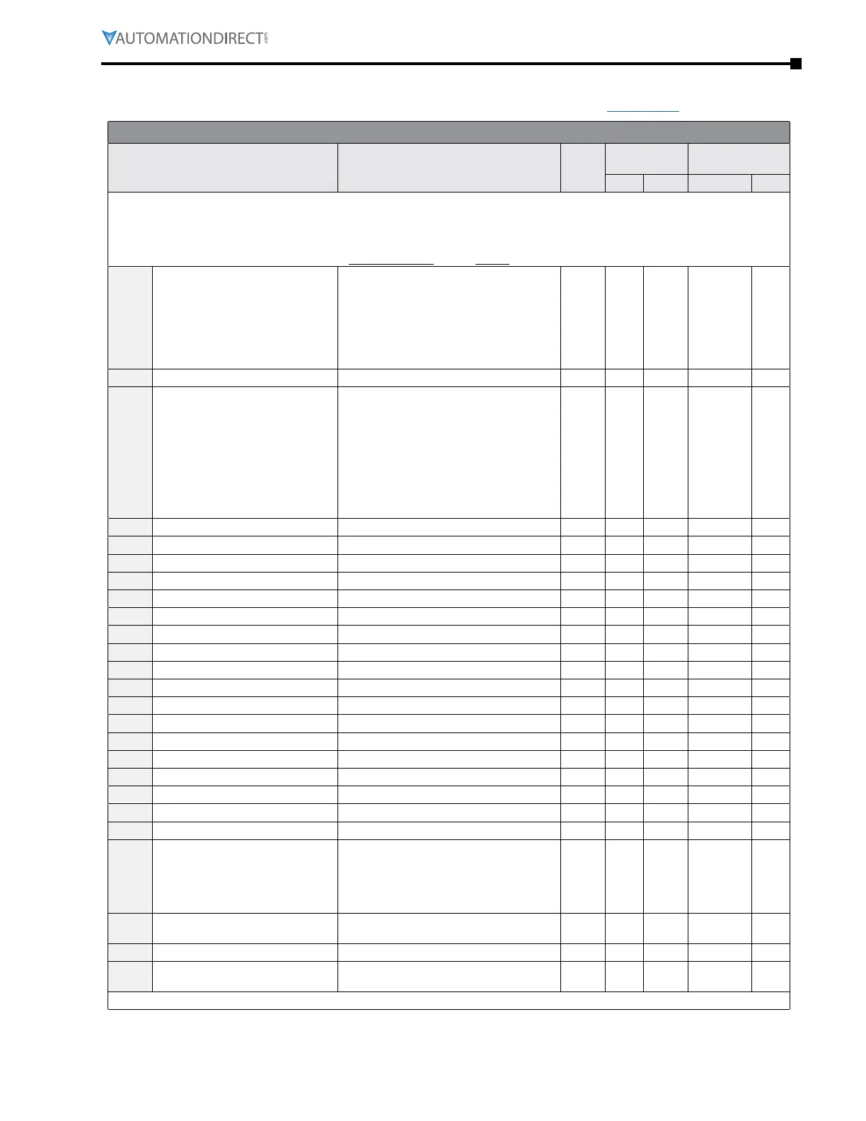
Pid ParaMeters suMMary (P7.xx)
For detailed information about the P7.xx parameter group, please refer to page 4–164.
GS4 Parameters Summary – PID Parameters (P7.xx)
Parameter Range
Run
1)
Read/
Write
Modbus
Address
Settings
Hex Dec Default
2)
User
1) ♦ in the Run-Read/Write column indicates that the parameter can be set during RUN mode.
R/W indicates “read/write.”
Read indicates “read-only.”
2) Parameters can be restored to their default values using P9.08.
P7.00
PID Action/Mode
0: PID Disabled
1: PID Reverse Local/Remote
2: PID Forward Local/Remote
3: PID Reverse Remote Only
4: PID Forward Remote Only
5: PID Reverse Local Only
6: PID Forward Local Only
♦R/W 0700 41793 0
P7.01
reserved ~ ~ 0701 41794 ~
P7.02
PID Setpoint Source Display
(when PID enabled, this
parameter data will be mapped
from P4�00~P4�01 dependent
upon whether in Remote=4�00 or
Local=4�01)
00: Keypad
01: RS485
02: AI1
03: AI2
04: AI3
05: Ext Up/Down Key
06: Comm Card
07: Multi-Step Inputs
08: PID off
Read 0702 41795 7
P7.03
PID Feedback Gain 0�00 to 300�00% ♦R/W 0703 41796 100�00
P7.04
PID Offset Value -100�0% to +100�0% ♦R/W 0704 41797 0�0
P7.05
Keypad PID Setpoint 0�00~100�00% Read 0705 41798 0�0
P7.06
PID Multi-Setpoint 1 0�00~100�00% ♦R/W 0706 41799 0�00
P7.07
PID Multi-Setpoint 2 0�00~100�00% ♦R/W 0707 41800 0�00
P7.08
PID Multi-Setpoint 3 0�00~100�00% ♦R/W 0708 41801 0�00
P7.09
PID Multi-Setpoint 4 0�00~100�00% ♦R/W 0709 41802 0�00
P7.10
PID Multi-Setpoint 5 0�00~100�00% ♦R/W 070A 41803 0�00
P7.11
PID Multi-Setpoint 6 0�00~100�00% ♦R/W 070B 41804 0�00
P7.12
PID Multi-Setpoint 7 0�00~100�00% ♦R/W 070C 41805 0�00
P7.13
Proportional Gain 0�0~100�0 ♦R/W 070D 41806 1�0
P7.14
Integral Time 0�00~100�00 sec ♦R/W 070E 41807 1�00
P7.15
Derivative Value 0�00~1�00 sec ♦R/W 070F 41808 0�00
P7.16
Upper Limit for Integral Time 0�0~100�0% ♦R/W 0710 41809 100�0
P7.17
Derivative Filter Time Constant 0�0~2�5 sec ♦R/W 0711 41810 0�0
P7.18
PID Output Frequency Limit 0�0~100�0% ♦R/W 0712 41811 100�0
P7.19
PID Feedback Value -200�00% to +200�00% Read 0713 41812 0�00
P7.20
Feedback Signal Detection Time 0�0~3600�0 sec ♦R/W 0714 41813 0�0
P7.21
PID Feedback Loss
0: Warn and Continue Operation
1: Warn (fault) and Ramp to Stop
2: Warn (fault) and Coast to Stop
3: Warn and Operate at Last Frequency
4: Warn and Run at P7�22
R/W 0715 41814 0
P7.22
PID Feedback Loss Speed Level
Default
0�00~400�00 Hz ♦R/W 0716 41815 0�00
P7.23
reserved ~ ~ 0717 41816 ~
P7.24
PID Offset Selection
0: Set by P7�04
1: Set by an AI Input
♦R/W 0718 41817 0
(table continued next page)

 Loading...
