Page 4–74
DURApulse GS4 AC Drive User Manual – 1st Ed, Rev A - 10/20/2017
Chapter 4: AC Drive Parameters
Type Hex Addr Dec Addr
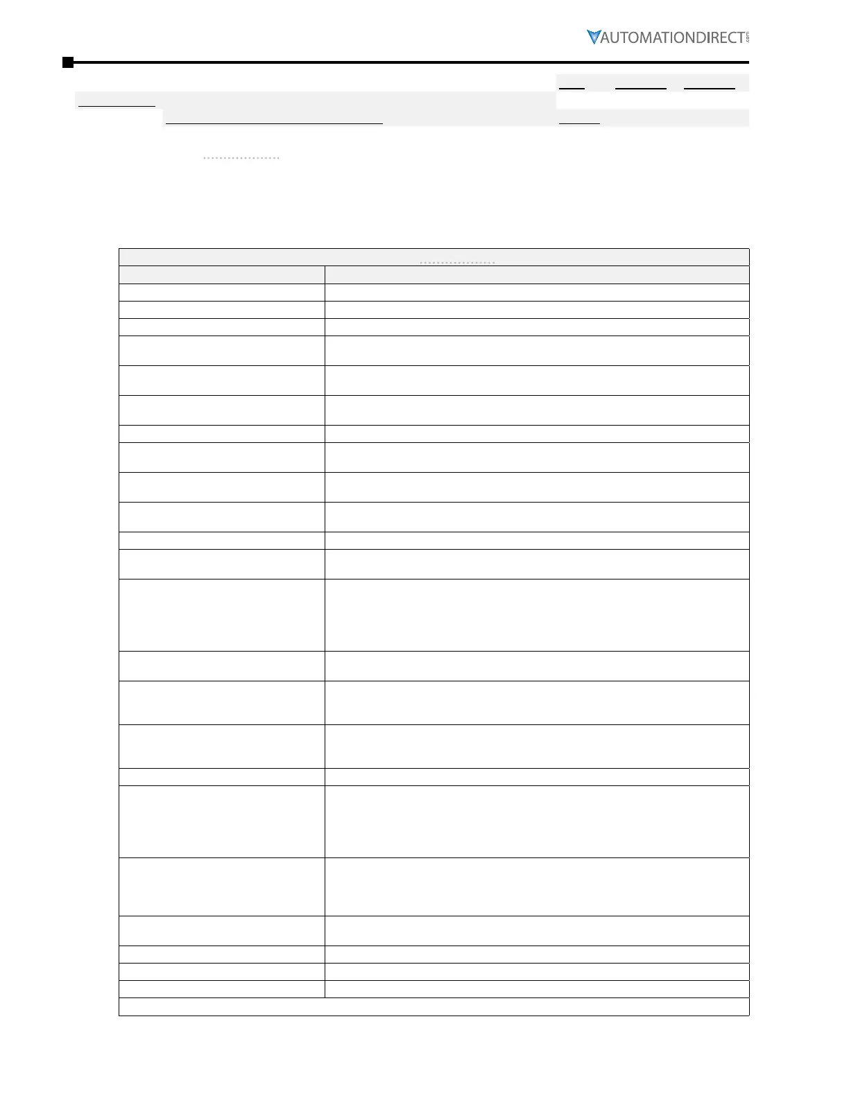
P3.17~P3.31 Multi-Function Output (MFO) Terminal Functions
♦R/W varies by parameter
Range/Units (Format: 16-bit unsigned) Default
0~55
(see P3�17~P3�31 Output Function Settings table below)
varies by parameter
These parameters set the functions of the Multi-Function output terminals.
•
If an MFO will not take a setting, then most likely the setting is already assigned to a different
output� MFO outputs also cannot be changed when the drive is running�
•
See Appendix C for digital and analog I/O worksheet�
Multi-Function Output Terminal Function Settings (P3.17~P3.31)
Setting: Function Function Description
0: No Function Output terminal has no function configured�
1: AC Drive Running Active when the drive is not at STOP�
2: At Frequency Setpoint Active when the GS4 drive reaches the output frequency setting�
3: At Speed 1 (P3�32)
Active when desired frequency #1 (P3�32) is attained� ON state frequency band
determined by P3�33�
4: At Speed 2 (P3�34)
Active when desired frequency #2 (P3�34) is attained� ON state frequency band
determined by P3�35�
5: At Zero Speed Including Drive
Running
Active when frequency command =0 and the drive is in RUN mode�
6: At Zero Speed Drive not Running Active when frequency command =0 or stop�
7: Over Torque Level 1
Active when detecting over-torque� Refer to P6�15 (over-torque detection level-
OT1) and P6�16 (over-torque detection time-OT1)� Refer to P6�14~P6�16�
8: Over Torque Level 2
Active when detecting over-torque� Refer to P6�18 (over-torque detection level-
OT2) and P6�19 (over-torque detection time-OT2)� Refer to P6�17~P6�19�
9: Drive Ready
Active when the drive is ON and no faults or abnormality detected� Drive is
ready for a start�
10: Low Voltage warning (Lv) Active when the DC Bus voltage is too low� (refer to P6�35 low voltage level)
11: Error indication (All faults, Except
for Lv Stop)
Active when fault occurs (except Lv stop)� Output will not deactivate until fault
is cleared and drive is reset back to ready state�
12: Brake release function
This function should be used with an external DC brake, and it is recommended
to use contact “b” (N�C) (P3�43)� This output turns ON at the beginning of the
accel ramp and turns OFF at the end of the decel ramp� To use the P3�51 Brake
Delay Timer, use MFO selection #42�
(See P3�51 for more details and timing diagrams�)
13: Over-temp warning
Active when IGBT or heat sink overheats� To prevent an OH fault from turning
off the output to the drive� (refer to P6�30 for OH warning level)
14: Dymamic braking output
Active when the dynamic brake function is ON� If DC Bus voltage is greater than
the braking voltage level set in parameter P6�28 (Dynamic Braking Voltage level),
then any output configured for function 14 will change state�
15: PID deviation error
Active when the feedback signal is abnormal� The output will be activated when
the GS4 drive exceeds the PID Deviation Level (P3�36) for longer than the PID
Deviation Time (P3�37)�
16: Over Slip (oSL) Active when the slip error is detected�
17: Mid-point Counter Value Attained
(P3�45)
Active when the counter reaches Middle Counter Value (P3�45)� This output
will only be active for the count number specified, once the counter input is
incremented one more count the output will be deactivated� DI6 must be
configured to 23 “Input Counter�” This output won’t activate if the middle
counter value is greater than final counter value�
18: Final Count Value Attained (P3�44)
Active when the counter reaches Final Counter Value (P3�44)� This output
will only be active for the count number specified, once the counter input is
deactivated from the achieved final count the count value will automatically
reset to 0� DI6 must be configured to 23 “Input Counter�”
19: Base Block Indication
Active when the output of the GS4 Drive is shut off during base block� A mulit-
function input must be configured to 11 “Base Block Inhibit�”
20: Warning Output Active when a warning is detected�
21: Overvoltage Alarm Active when an over-voltage is detected�
22: Oc Stall Alarm Active when an over-current stall prevention is detected�
(table continued next page)

 Loading...
