Chapter 4: AC Drive Parameters
Page 4–75
DURApulse GS4 AC Drive User Manual – 1st Ed, Rev A - 10/20/2017
Multi-Function Output Terminal Function Settings (P3.17~P3.31) (continued)
Setting: Function Function Description
23: Ov Stall Alarm Active when an over-voltage stall prevention is detected�
24: External Control Mode
Active when the operation command (P3�00, P3�01) is controlled by RS-485,
External Terminals, or Communication Card� This setting takes into account if
the drive is in LOCAL or REMOTE mode� The drive does not need to be running
for this output to energize�
25: Forward Command
Active when the commanded drive direction is forward� Does not indicate
actual direction of rotation of motor� If motor is running REV and then
commanded to run FWD this output will turn on, but the motor will still need
time to ramp down in order to change direction�
26: Reverse Command
Active when the commanded drive direction is reverse� Does not indicate actual
direction of rotation of motor� If motor is running FWD and then commanded
to run REV this output will turn on, but the motor will still need time to ramp
down in order to change direction�
27: Above Desired Current (≥ P3.52) Active when current is ≥P3.52.
28: Below Desired Current (< P3�52) Active when current is <P3�52�
29: Wye Connected Command
Used to trigger the switching contactors for a Wye-connected motor when
switching from Wye to Delta starting of a motor� Use P2�20~P2�22 to enable
and set up this feature� Two digital inputs must be set to 27 and 28�
30: Delta Connected Command
Used to trigger the switching contactors for a Delta-connected motor when
switching from Wye to Delta starting of a motor� Use P2�20~P2�22 to enable
and set up this feature� Two digital inputs must be set to 27 and 28�
31: Zero Speed at Drive Running
Active when the actual output frequency is 0� (The drive should be in RUN
mode�)
32: Zero Speed including Drive Stop Active when the actual output frequency is 0 or Stop�
33: Fault Option 1 (P11�00) Active when fault group selected in P11�00 is ON�
34: Fault Option 2 (P11�01) Active when fault group selected in P11�01 is ON�
35: Fault Option 3 (P11�02) Active when fault group selected in P11�02 is ON�
36: Fault Option 4 (P11�03) Active when fault group selected in P11�03 is ON�
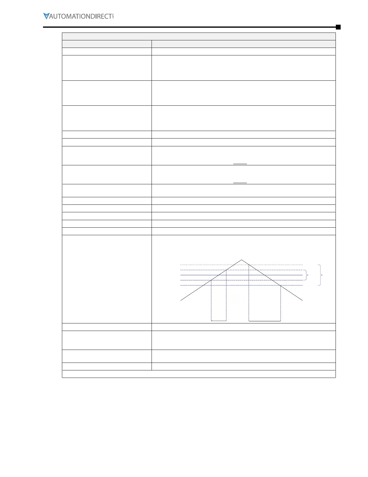
37: At Speed (Setpoint include 0Hz)
Active when the output frequency reaches frequency setting including an output
frequency of 0Hz� The output will be activated when the output frequency
reaches ±2Hz of the At Speed Setpoint, and go off when the frequency exceeds
±4Hz of the At Speed Setpoint value�
ON
Output
Frequency
Commanded
Frequency
±2Hz
±4Hz
Multi-function Output
P3.17~P3.33 = 37
OFF
38: reserved n/a
39: Under Ampere (Low Current)
This function needs to be used with P6�52, P6�53, P6�54� If P6�54 is not 0, the
corresponding multi-function terminal will be ON if the current is less than
P6�52 level and time elapsed is greater than P6�53�
40: UVW Motor Contactor ON
Set an MFI=34 (drive enable) and MFO=40 (Motor Contactor ON)� The
magnetic contactor will then follow the drive enable status�
41: DEB Active (Decel Energy Backup) Active when DEB activation is on�
(table continued next page)

 Loading...
