Page 4–76
DURApulse GS4 AC Drive User Manual – 1st Ed, Rev A - 10/20/2017
Chapter 4: AC Drive Parameters
Multi-Function Output Terminal Function Settings (P3.17~P3.31) (continued)
Setting: Function Function Description
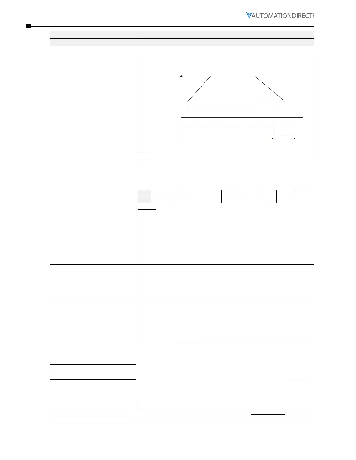
42: Brake Released at Stop
(Brake Engaged During Decel)
This function is typically used in conjunction with a mechanical brake�
When drive stops, the corresponding Multi-Function Output terminal will be ON
if the frequency is less than P3�53� After it is ON, the output will turn OFF when
brake delay time exceeds P3�51�
Multi-function
Output
P3.17~P3.33
Run
Frequency
Output
Frequency
< P3.53
P3.51
RUN
Note: With a long deceleration and a short brake time, the output could energize
(for P3.51) and de-energize before the ramp is complete.
43: RS485 Digital Output
Enables user control of an output via RS-485� When the MFO is set to 43,
writing to the correct bit in address 2640h (Modbus 49793) will turn on the
associated output� This address will reset to zero when written to via RS-485
(but the output will stay ON because the bit was set)� Digital Output Status
should always be read from P3�47 (Modbus decimal address 40816)�
Bit 0 1 2 3 4 5 6 7 8 9
Out R1 R2 xx DO1 DO2 DO10 DO12 DO13 DO14 DO15
Example:
Set P3�17 = 43 (Sets R1 to RS485 Digital Output)
Write a 1 to Bit 0 of 49793� R1 will turn ON�
Bit 0 of 49793 will read 0 (49793 auto-resets to 0)�
Bit 0 of 40816 (P3�47 Digital Output Status) will read 1�
Write a 0 to Bit 0 of 49793 to turn R1 OFF�
44: COMM Card Digital Output
Allows user to control Digital Outputs via Ethernet Comm Card� Each output
has a corresponding bit in 40793� Only writes from the Ethernet card will cause
the output to turn ON if #44 is selected� The value in 40793 is maintained when
written to over Ethernet�
45: Fire Mode Indication
An activation of setting 45 indicates fire mode is active� Requires Multi-Function
Input P3�03~3�16 configured for 40: Fire Mode with RUN Command, or 41: Fire
Mode without RUN Command� Requires Fire Mode P6�55 to be enabled�
When the DI for Fire Mode turns ON, the DO associated with this input will also
turn ON� The output is not retentive; the output turns ON and OFF with the Fire
Mode DI�
46: Fire Bypass Indication
Requires Fire Mode Enable Bypass P6�57 to be enabled� The bypass will activate
after the Bypass Delay Time� Once Fire Mode input is turned OFF, the bypass
will be turned OFF�
Only certain types of faults are able to be bypassed in Fire Mode�
The list of fault codes, including which ones can and cannot be bypassed in
Fire Mode, is shown in the "Fault Codes" table in Chapter 6: Maintenance and
Troubleshooting (page 6–16)�
47: Motor #1 Selected
When setting multi-motor circulative function, the Multi-Function Output
terminal will automatically set up P3�17(R1), 3�18(R2), and P3�21(R10)~P3�26(R15)
in accordance with P10�01’s (Number of Connected Motors) setting (page 4–195)�
48: Motor #2 Selected
49: Motor #3 Selected
50: Motor #4 Selected
51: Motor #5 Selected
52: Motor #6 Selected
53: Motor #7 Selected
54: Motor #8 Selected
55: Mtr1/Mtr2 Nameplate Parameters Indicates which motor is selected from P0�10 or MFI setting 14�
56: Safety STO A Normally Open Auxiliary output for STO indication� Not safety rated�
(table continued next page)

 Loading...
