Chapter 4: AC Drive Parameters
Page 4–77
DURApulse GS4 AC Drive User Manual – 1st Ed, Rev A - 10/20/2017
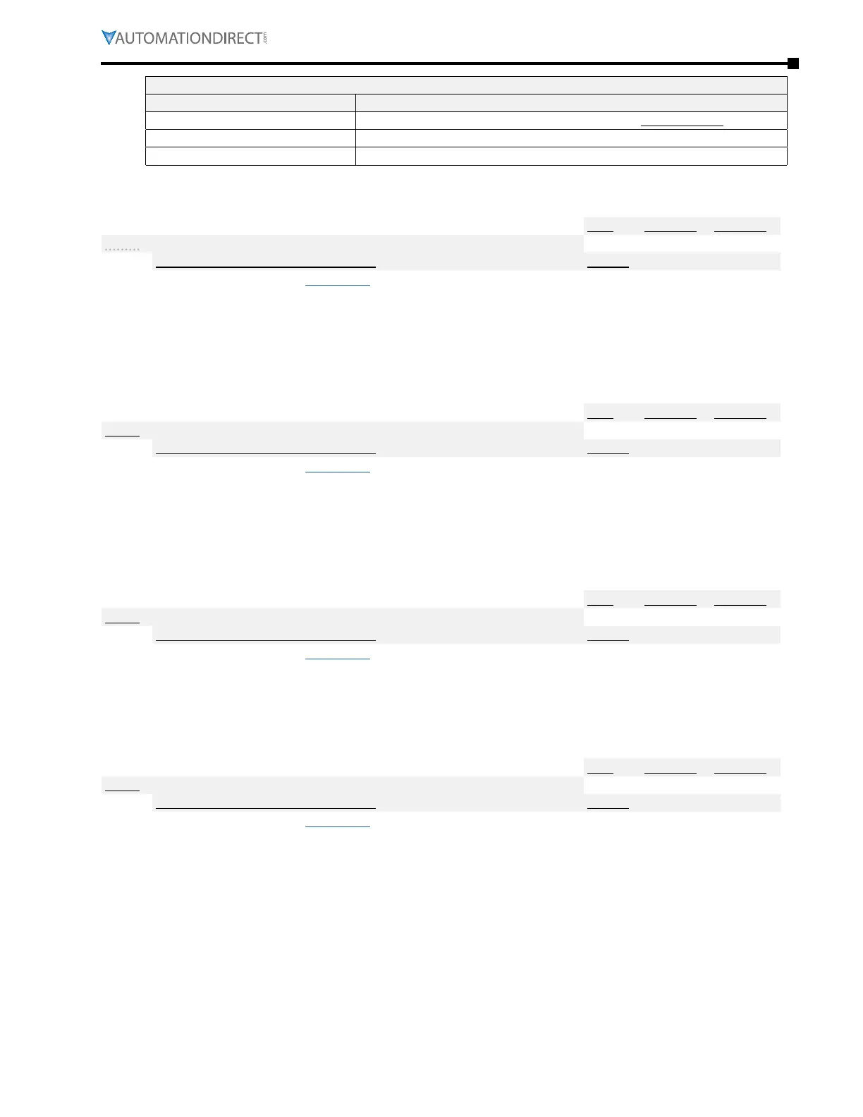
Multi-Function Output Terminal Function Settings (P3.17~P3.31) (continued)
Setting: Function Function Description
57: Safety STO B Normally Closed Auxiliary output for STO indication� Not safety rated�
58: Frequency Output Above P3�53 Active when current frequency output is ≥ the value in P3.53.
59: Frequency Output Below P3�53 Active when current frequency output is < the value in P3�53�
Type Hex Addr Dec Addr
P3.17 Multi-Function Output Terminal 1 (Relay 1) or (PLC Y0)
♦R/W 0311 40786
Range/Units (Format: 16-bit unsigned) Default
Same as P3�17~P3�31 (page 4–74)
11
This parameter (P3.17) sets the function of Multi-Function Output Terminal 1 (Relay 1).
Relay 1 (R1) has a normally open (R1O) and normally closed (R1C) dry contact located on the drive
terminal board.
•
Represented by Bit 0 on the “DO Status” (P3�47) bit map�
•
NO/NC behavior is controlled by Bit 0 in P3�43�
Type Hex Addr Dec Addr
P3.18 Multi-Function Output Terminal 2 (Relay 2) or (PLC Y1)
♦R/W 0312 40787
Range/Units (Format: 16-bit unsigned) Default
Same as P3�17~P3�31 (page 4–74)
1
This parameter sets the function of Multi-Function Output Terminal 2 (Relay 2).
Relay 2 (R2) has a normally open (R2O) and normally closed (R2C) dry contact located on the
drive.
•
Represented by Bit 1 on the “DO Status” (P3�47) bit map�
•
NO/NC behavior is controlled by Bit 1 in P3�43�
Type Hex Addr Dec Addr
P3.19 Multi-Function Output Terminal 3 (DO1) or (PLC Y3)
♦R/W 0313 40788
Range/Units (Format: 16-bit unsigned) Default
Same as P3�17~P3�31 (page 4–74)
0
This parameter sets the function of Multi-Function Output Terminal 3 (DO1).
DO1 can be wired for a sink or source configuration, and is located on the drive.
•
Represented by Bit 3 on the “DO Status” (P3�47) bit map�
•
NO/NC behavior is controlled by Bit 3 in P3�43�
Type Hex Addr Dec Addr
P3.20 Multi-Function Output Terminal 4 (DO2) or (PLC Y4)
♦R/W 0314 40789
Range/Units (Format: 16-bit unsigned) Default
Same as P3�17~P3�31 (page 4–74)
0
This parameter sets the function of Multi-Function Output Terminal 4 (DO2).
DO2 can be wired for a sink or source configuration, and is located on the drive.
•
Represented by Bit 4 on the “DO Status” (P3�47) bit map�
•
NO/NC behavior is controlled by Bit 4 in P3�43�

 Loading...
