Chapter 4: AC Drive Parameters
Page 4–139
DURApulse GS4 AC Drive User Manual – 1st Ed, Rev A - 10/20/2017
Type Hex Addr Dec Addr
P6.27 Over-Voltage Stall Prevention Level
♦R/W 061B 41564
Range/Units (Format: 16-bit unsigned) Default
230V: 300�0~450�0 VDC
460V: 600�0~900�0 VDC
390�0
780�0
Sets the voltage level of the DC bus when overvoltage stall prevention is activated.
During deceleration, the DC bus voltage may exceed its Maximum Allowable Value due to motor
regeneration. When this function is enabled (Over-Voltage Stall Prevention P6.11=00), the drive
will not decelerate further and will keep the output frequency constant until the voltage drops
below the preset value again (P6.27).
This function is used if there is a potential for high load inertia. When stopping a normal load, an
over-voltage won’t occur during deceleration, and deceleration time will be followed. If the load
has a high inertia, the GS4 drive may not stop the motor due to over-voltage during deceleration.
During this situation drive will auto adjust the deceleration time until drive stops.
When the over-voltage stall prevention is enabled, drive deceleration time could be longer than
the decel setting.
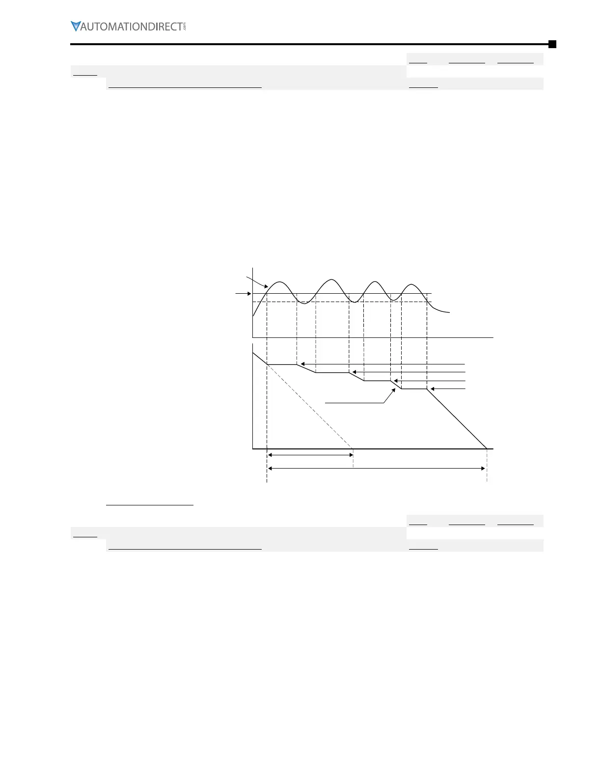
Output Frequency
Deceleration characteristics
when over-voltage stall
prevention enabled
Frequency Held
Previous decel time
Time
Time
High Voltage at DC side
Over-Voltage Detection Level
required time for decelerating to 0Hz when
over-voltage stall prevention is enabled
Related parameters: P1.29, P6.11, P6.12 (decel times: P1.02, P1.04, P1.06, or P1.08)
Type Hex Addr Dec Addr
P6.28 Dynamic Braking Voltage Level
♦R/W 061C 41565
Range/Units (Format: 16-bit unsigned) Default
230V: 350�0~450�0 VDC
460V: 700�0~900�0 VDC
390�0
780�0
This parameter establishes the Dynamic Braking Voltage Level threshold based on the DC Bus
voltage. With the drive running and with DC Bus voltage above the braking level threshold, the
braking transistor internal to the drive is gated ON, connecting the external braking resistor across
the DC Bus to dissipate the excess voltage as heat.
Refer to Appendix A, Accessories, for detailed information on braking resistors.
Parameter P6.28 is valid only for the models below 40hp for 460 series and 30hp for 230 series
(unless a braking resistor is used, in which case larger model drives can be used). Larger GS4
models use external dynamic braking units (DBUs) to determine dynamic braking voltage level.
 Loading...

