Page 4–192
DURApulse GS4 AC Drive User Manual – 1st Ed, Rev A - 10/20/2017
Chapter 4: AC Drive Parameters
block transFer exPlanation
Parameters P9.09~P9.24 and P9.69~P9.84
Block Transfer allows parameters from many different Parameter Groups to be consolidated into
one Modbus communication message. This can greatly simplify PLC programming and reduce
network traffic. Unlike previous GS drives*, the GS4 has two sets of Block Transfer Parameters:
A) New Pointer Parameters P9.69~P9.84 (where you enter the addresses that you want to
consolidate)
B) Data Location Parameters P9.09~P9.24 (where you push data into, or pull data out of)
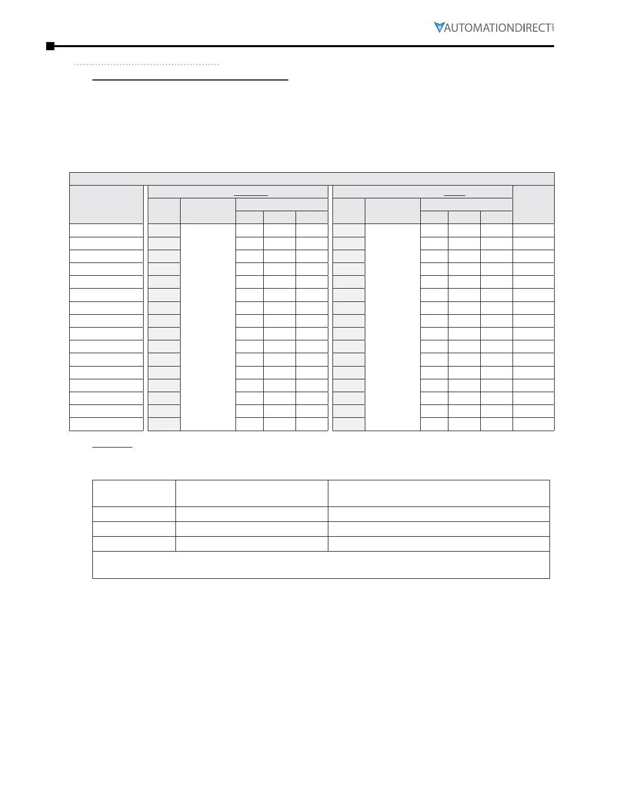
GS4 Parameters Summary – Serial Communication Parameters – Block Transfer Parameter Map
Parameter
/ Address
Description
Block Transfer Address Pointers Block Transfer Data
Default
Setting
Para-
meter
Description
(Range)
Modbus Address
Para-
meter
Description
(Range)
Modbus Address
Hex Dec Octal Hex Dec Octal
Block Transfer 1
P9.69
0~65535
Format as
xxyy, where:
xx = target
parameter
group #
yy = target
parameter #
0945 42374 4505
P9.09
Dependent
upon the
target
address�
Example:
If Block
Transfer
points to
a digital
parameter,
range = 0,1�
If it points
to analog
parameter,
the range
could be
0–65535�
0909 42314 4411 0
Block Transfer 2
P9.70
0946 42375 4506
P9.10
090A 42315 4412 0
Block Transfer 3
P9.71
0947 42376 4507
P9.11
090B 42316 4413 0
Block Transfer 4
P9.72
0948 42377 4510
P9.12
090C 42317 4414 0
Block Transfer 5
P9.73
0949 42378 4511
P9.13
090D 42318 4415 0
Block Transfer 6
P9.74
094A 42379 4512
P9.14
090E 42319 4416 0
Block Transfer 7
P9.75
094B 42380 4513
P9.15
090F 42320 4417 0
Block Transfer 8
P9.76
094C 42381 4514
P9.16
0910 42321 4420 0
Block Transfer 9
P9.77
094D 42382 4515
P9.17
0911 42322 4421 0
Block Transfer 10
P9.78
094E 42383 4516
P9.18
0912 42323 4422 0
Block Transfer 11
P9.79
094F 42384 4517
P9.19
0913 42324 4423 0
Block Transfer 12
P9.80
0950 42385 4520
P9.20
0914 42325 4424 0
Block Transfer 13
P9.81
0951 42386 4521
P9.21
0915 42326 4425 0
Block Transfer 14
P9.82
0952 42387 4522
P9.22
0916 42327 4426 0
Block Transfer 15
P9.83
0953 42388 4523
P9.23
0917 42328 4427 0
Block Transfer 16
P9.84
0954 42389 4524
P9.24
0918 42329 4430 0
Example:
You want to consolidate the parameters Multi-Speed 15 (P5.15), Skip Frequency 3 Lower Limit
(P1.24), and Circulation Time (P10.02). Enter the following values into P9.69, P9.70, and P9.71:
Address Pointers
Data Locations
(to Push Data to, or Pull Data from)
Block Transfer 1 P9�69 = 515 (points to P5�15) P9�09
Block Transfer 2 P9�70 = 124 (points to P1�24) P9�10
Block Transfer 3 P9�71 = 1002 (points to P10�02) P9�11
The Address Pointers use xxyy format, where: • xx = Parameter Group# and
• yy = Parameter# in that group.
All of the data is now in consecutive order so that you can write one Modbus message to P9.09
with a length of three registers, and it will change P5.15, P1.24, and P10.02. Or you can use one
Modbus Read message that will collect all three parameters at once. Without Block Transfer,
reading or writing these three parameters would require three separate communication
commands from an external PLC.
* Previous GS Drives had only one set of parameters for Block Transfer, and the Pointer Addresses had
to be manually entered into the keypad. Only then would any read or write into that Block Transfer
address actually be linked to the desired data. Unfortunately, this meant that you would have to
manually enter Block Transfer addresses via the keypad for any new drive. With the GS4 method, the
Pointer Addresses are in separate parameters. Thus, the complete configuration can be downloaded
via software (no keypad entry necessary).

 Loading...
