89000109-002 xVue Touch Installation Manual
Rev 2 Page 5-9
© Honeywell International Inc. Do not copy without express permission of Honeywell.
For Use in Non-Certified Aircraft
5.3.3 KG 71EXP Maintenance Port
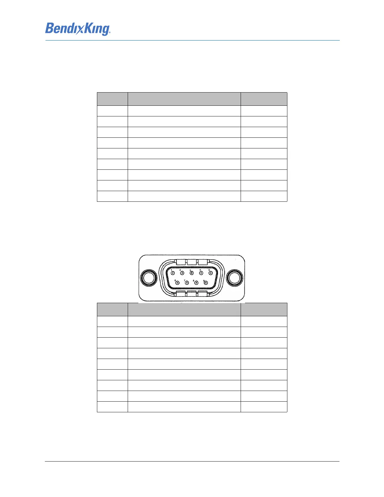
The maintenance port pinout uses a standard PC COMM Port connector, female D-Sub. Details about the
maintenance port, J2, interface are shown in Table 5-6 KG 71EXP Maintenance Port Pin Descriptions
(Viewed from LRU).
5.4 KMG 7010
The electrical interface for the KMG 7010 is provided via the 9 pin DB-9 connector referenced as J7010.
Details about the J7010 connector interface are shown in Table 5-7
Table 5-7 KMG 7010 DB-9 Pin Descriptions (Viewed from LRU)
Table 5-6 KG 71EXP Maintenance Port Pin Descriptions (Viewed from LRU)
J2 Pin Description I/O
1Spare -
2 Serial Channel 0 RX data In
3 Serial Channel 0 TX data Out
4Spare -
5Ground GND
6Spare -
7 Serial Channel 0 Request to Send Out
8 Serial Channel 0 Clear to Send In
9Spare -
J7010 Pin Description I/O
1AC Power In
2Spare -
3 CAN Bus Hi In/Out
4 CAN Bus Hi In/Out
5 CAN Bus Lo In/Out
6Power Ground GND
7 Chassis Ground GNS
8Spare -
9 CAN Bus Lo In/Out