89000109-002 xVue Touch Installation Manual
Rev 2 Page 4-9
© Honeywell International Inc. Do not copy without express permission of Honeywell.
For Use in Non-Certified Aircraft
(5) Secure the DB-78 J1 and J2 connectors, to the KSD 100EXP (refer to Figure 4-1 KSD 100EXP (Back
View)). Torque the four jack post connector screws (two per connector) to 4 ± 0.4 in-lbs (0.45 ±
0.05 Nm).
(6) Verify the electrical bond between the backshell and the KSD 100EXP conforms to the guidelines
listed in Section 3.10 Electrical Bonding Considerations.
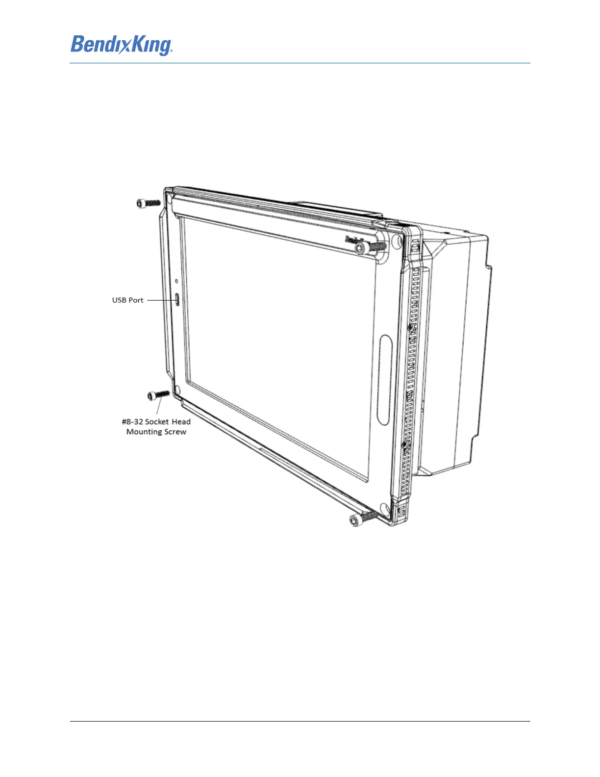
(7) Install the KSD 100EXP into the instrument panel while ensuring that the USB port is located on
the left side of the unit (from the pilot’s perspective) and secure using the four #8-32 socket head
mounting screws. Torque screws to 20 ± 2 in-lbs (2.26 ± 0.22 Nm).
Figure 4-11 KSD 100EXP Installation
(8) Verify the electrical bond between the KSD 100EXP and the airplane instrument panel conforms
to the guidelines listed in 3.10 Electrical Bonding Considerations.
4.3.3 KSD 100EXP Installation Unit Verification
Complete the KSD 100EXP System Configuration procedure in Section 6.2 prior to executing post
installation checkout documented in Section 7.