89000109-002 xVue Touch Installation Manual
Rev 2 Page 5-11
© Honeywell International Inc. Do not copy without express permission of Honeywell.
For Use in Non-Certified Aircraft
5.6 KDC 100EXP
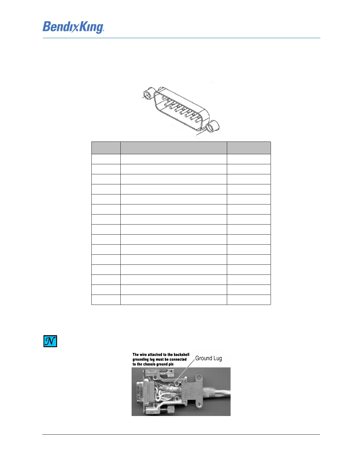
The electrical interface for the KDC 100EXP is provided via the 15 pin DB-15 connector.Details about the
connector interface are shown in Table 5-9.
Table 5-9 KDC 100EXP Pin Descriptions (Viewed from LRU)
Figure 5-3 KDC 100EXP Backshell
Pin Description I/O
1 Magnetometer 429 RX HI In
2 Magnetometer 429 RX LO In
3Ground NC
4 Magnetometer CAN LO Bi-Direction Out
5 Magnetometer CAN HI Bi-Direction Out
6Ground NA
7 Maintenance RS232 Tx Out
8 Maintenance RS232 Rx In
9 Maintenance RS232 Gnd Gnd
10 Not Used NC
11 Not Used NC
12 Not Used NC
13 Not Used NC
14 Power-In-Rtn In
15 Power-In In
NOTE
SHIELD WIRING MUST REMAIN IN BACKSHELL (CONNECT TO GROUND LUG INSIDE
BACKSHELL).