89000109-002 xVue Touch Installation Manual
Rev 2 Page 4-3
© Honeywell International Inc. Do not copy without express permission of Honeywell.
For Use in Non-Certified Aircraft
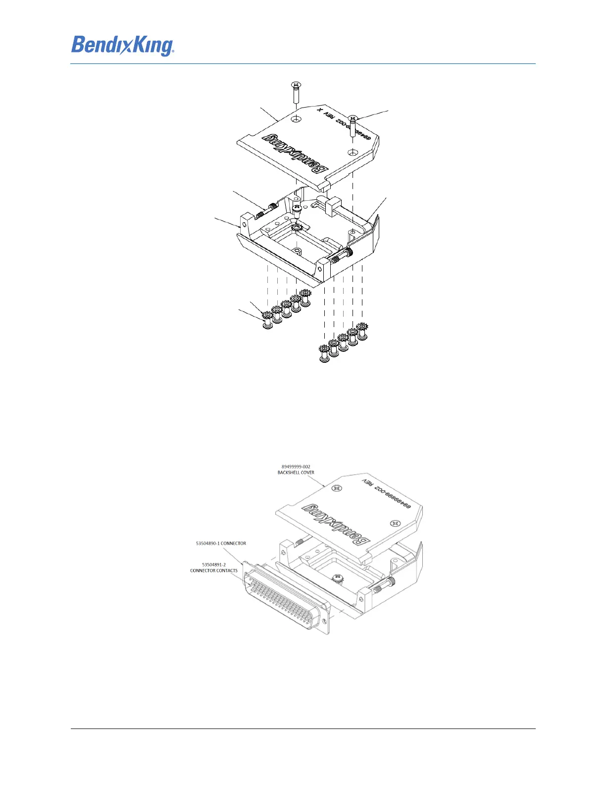
Figure 4-2 BendixKing Backshell Assembly
4.3.1.1 J1 Connector Assembly
The KSD 100EXP J1 Connector mounts to the upper D-Sub receptacle (P1) on the back of the KSD 100EXP.
See Figure 4-2 and Figure 4-3 for exploded view diagrams and part descriptions. See Table 5-1 KSD
100EXP J1 Pin Descriptions (Viewed from LRU) for pin designations.
Figure 4-3 KSD 100EXP J1 Connector Assembly
Using the KSD 100EXP Installation Kit - Backshell Assembly and the KSD 100EXP Installation Kit -
Configuration Module and Connectors:
(1) Prepare the J1 wire harness by stripping wire ends and applying crimped pin connector contacts.
89499999-002 BACKSHELL
COVER (QTY 2)
MS51959-17 SCREWS (QTY 4)
MS3367-7-9 TIEDOWN
STRAP (QTY 2)
7024206-10 SOCKET HEAD
CAP SCREW (QTY 4)
894 99 999-003 BACKSHELL
BASE (QTY 2)
MS35335-57 LOCK
WASHER (QTY 22)
MS5 1957-13
SCREW (QTY 22)