89000109-002 xVue Touch Installation Manual
Rev 2 Page 5-6
© Honeywell International Inc. Do not copy without express permission of Honeywell.
For Use in Non-Certified Aircraft
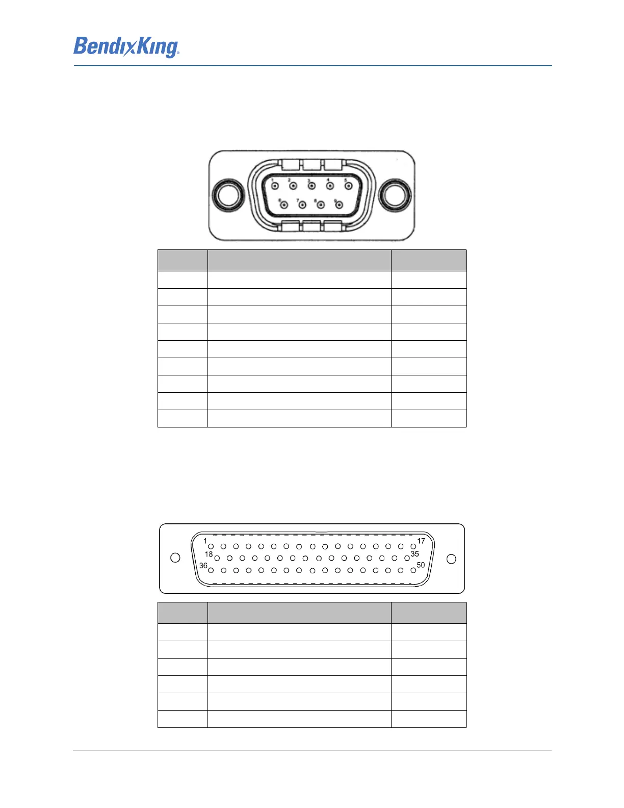
5.2 KCP 100EXP
Input/Output data and power to the KCP 100EXP is transmitted and received through an RS-232
interface, 9-pin male DB-9 connector referenced as J1.
Table 5-3 KCP 100EXP J1 Pin Descriptions (Viewed from LRU)
5.3 KG 71EXP
5.3.1 KG 71EXP Connector – J71
The electrical interface for the KG 71EXP is provided via the 50 pin D-Sub connector referenced as J71.
Table 5-4 KG 71EXP J71 Pin Descriptions (Viewed from LRU)
J1 Pin Description I/O
1Ground GND
2 RS232_TX_OUT Out
3 RS232_RX_IN In
4Spare -
5Ground GND
6Spare -
7Spare -
8 15VDC_PWR_RTN GND
9 15VDC_PWR_IN PWR
J71 Pin Description I/O
1 Power Input In
2 Power Input In
3 Power Input (Spare) In
4Spare N/A
5 Attitude Valid Out
6Excitation Wave 26VAC In