89000109-002 xVue Touch Installation Manual
Rev 2 Page 4-2
© Honeywell International Inc. Do not copy without express permission of Honeywell.
For Use in Non-Certified Aircraft
(7) Install four #4-40 nutplates on the back side of the instrument panel at the KCP 100EXP mounting
hole locations provisioned in steps (4)and (5).
(8) Finish the instrument panel as needed and install in airplane.
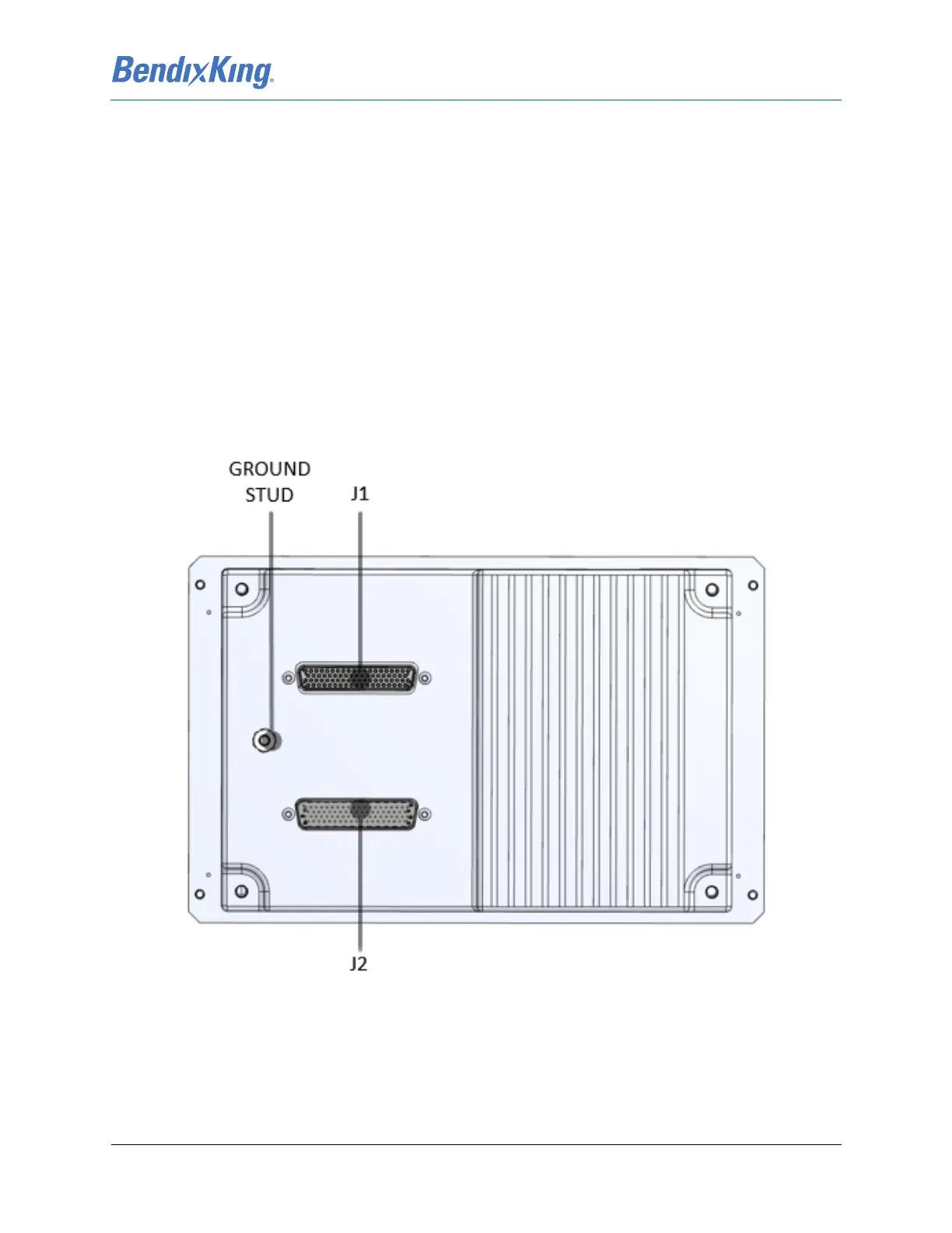
4.3 KSD 100EXP Installation
4.3.1 KSD 100EXP Connectors/Configuration Module
The J1 and J2 LRU connectors attach to the P1 (upper) and P2 (lower) wiring harness connectors; refer to
Figure 4-1. Each 78-pin D-sub connector housing, provided in the KSD 100EXP Installation Kit -
Configuration Module And Connectors, is mounted inside a BendixKing Backshell Assembly, provided in
the KSD 100EXP Installation Kit - Backshell Assembly. See Figure 4-2 for exploded view diagram and part
number references of the backshell assembly.
The Configuration Module is a circuit card assembly (CCA) provided in the KSD 100EXP Installation Kit -
Configuration Module. The Configuration Module is installed in the J2 connector. See Section 4.3.1.2 for
Configuration Module installation instructions.
Figure 4-1 KSD 100EXP (Back View)