8
Commissioning
70/130 ekr CON 100 – Installation and Operating Manual
When new position values are taught in, the factory default set-
tings will be overwritten. The relevant symbol (sensor 1, sensor 2
or servo-center position) will be inversely displayed after teaching
in a new value.
WARNING
Danger of death from actuator movements!
During function tests, parts of your body may be crushed, cut or hit.
►
Make sure that no persons remain in the vicinity of the pivot /
traversing area of machine components that are positioned by
the actuator.
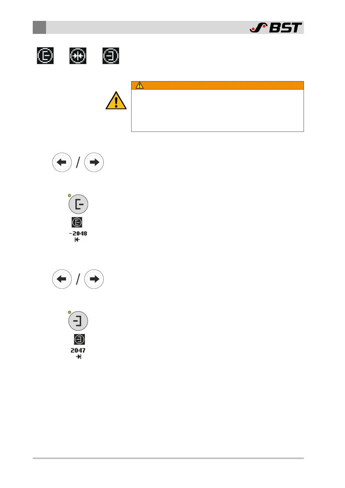
Setting the position for the software limit switch 1
1. Using the arrow keys, move the guiding device to the desired
position for software limit switch 1 (in the direction of sensor 1).
The position indicator of the actuator displays the value supplied
by the position feedback.
2. Press the Sensor 1 key.
The position for software limit switch 1 is stored.
The symbol Sensor 1 will be inversely displayed.
The new position for software limit switch 1 appears under the
symbol.
Setting the position for the software limit switch 2
1. Using the arrow keys, move the guiding device to the desired
position for software limit switch 2 (in the direction of sensor 2).
The position indicator of the actuator displays the value supplied
by the position feedback.
2. Press the Sensor 2 key.
The position for software limit switch 2 is stored.
The symbol Sensor 2 will be inversely displayed.
The new position for software limit switch 2 appears under the
symbol.

 Loading...


