110
Auxiliary functions
26.2.5. SPLTRNG – Signal split range
Min. and max. values of the input signal as % for which the valve runs through the entire stroke range.
Factory setting: Min = 0 %; Max = 100 %
Type 8793: The SPLTRNG auxiliary function can only be selected when operating as a positioner.
P.CONTROL = not activated.
Use this auxiliary function to limit the position set-point value range of the Type 8792/8793 by specifying a minimum
and a maximum value.
As a result, it is possible to divide a utilised standard signal range (4 – 20 mA; 0 – 20 mA; 0 – 10 V or 0 – 5 V) into
several devices (without or with overlapping).
This allows several valves to be used alternately or in the case of overlapping set-point value ranges simultane-
ously as actuating element.
EXIT
*
OK
Enter
value
Enter
value
SPLTRNG
Min 0 %
Max 100 %
Input the minimum value of the
input signal as %.
Adjustment range: 0 – 75 %
Input the maximum value of the
input signal as %.
Adjustment range: 25 – 100 %
ENTER INPUT
INPUT
* If the submenu is left by pressing the
ESC
key, the value remains unchanged.
Figure 61: Operating structure SPLTRNG
The changed data is saved in the memory (EEPROM) only when there is a switch to the process level,
by leaving the main menu (MAIN) using the left selection key
EXIT
. During the save process, the save
symbol is indicated
on the display.
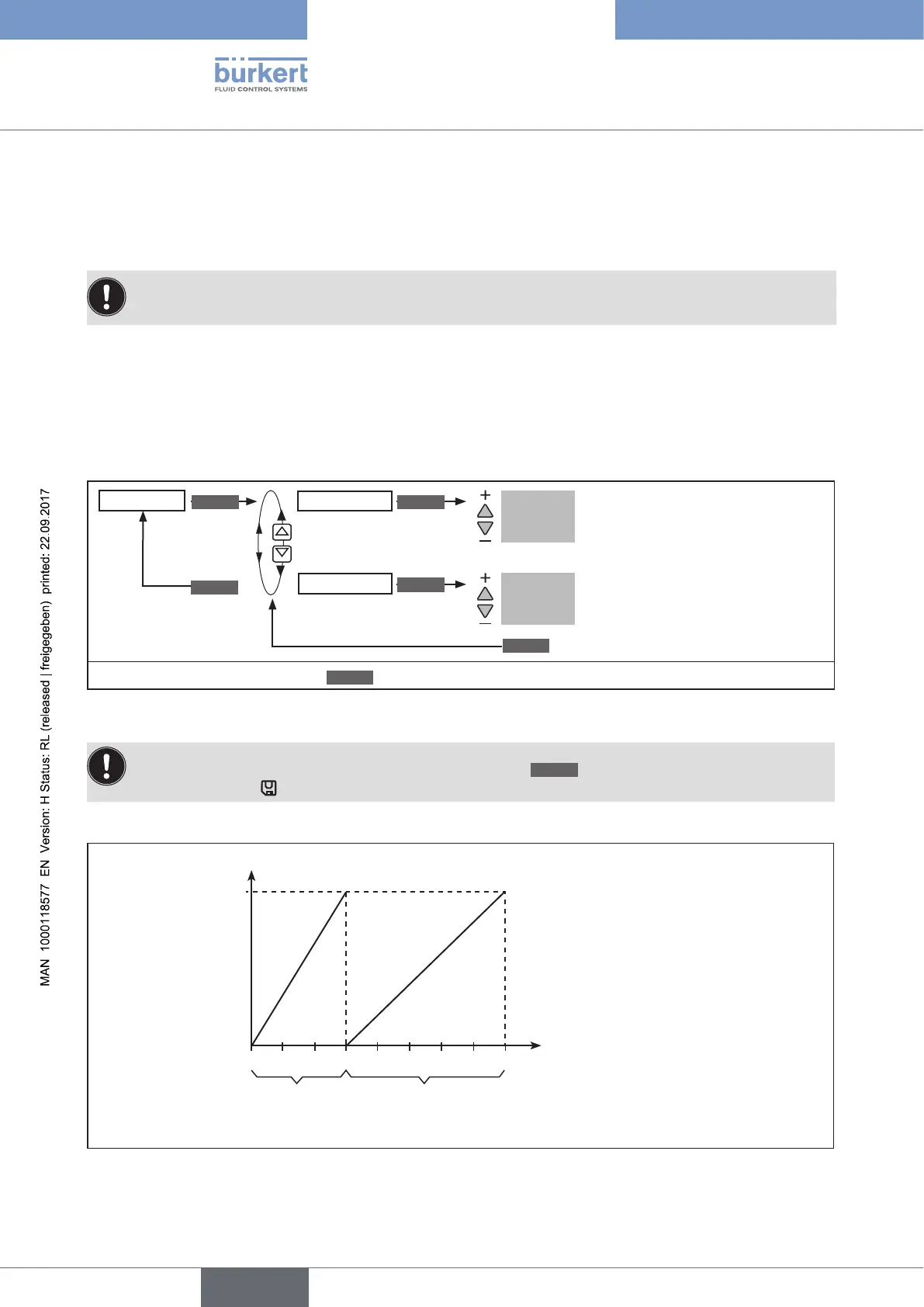
Splitting a standard signal range into two set-point value ranges
4
6 8 10
12 14 16 18 20
100
Valve stroke [%] (POS)
Set-point value [mA]
(INP)
Set-point value range
Positioner 1
Set-point value range
Positioner 2
Figure 62: Graph - SPLTRNG