17
Description of System
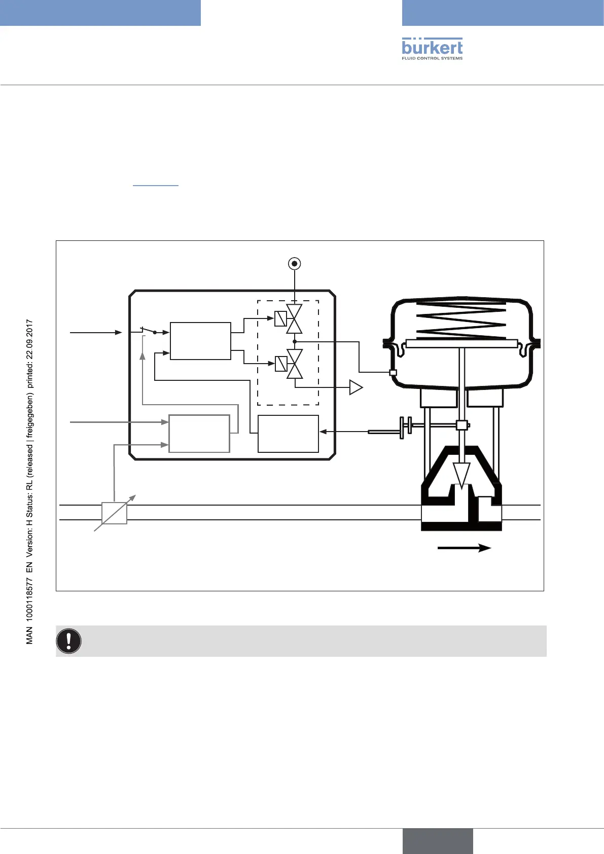
6.2. Function diagram
6.2.1. Diagram illustrating single-acting actuator
The black lines in “Figure 2” specify the function of the positioner circuit in Type 8792.
The grey part of the diagram indicates the additional function of the superimposed process control circuit in Type
8793.
* Control system
1: Aeration valve
2: Bleed valve
Compressed-
air supply
Position
sensor
Process
controller
Positioner
Control
system*
1
2
Process
set-point
value
Process
actual
value
Position set-
point value
Exhaust air
Type 8792 / 8793
Continuous valve with
single-acting actuator
Sensor
Actual position
Nominal position
Figure 2: Structure, positioner Type 8792 / process controller 8793
The remote design has the position sensor situated outside the device directly on the continuous valve
and is connected to the latter by a cable.