189
PROFIBUS DP
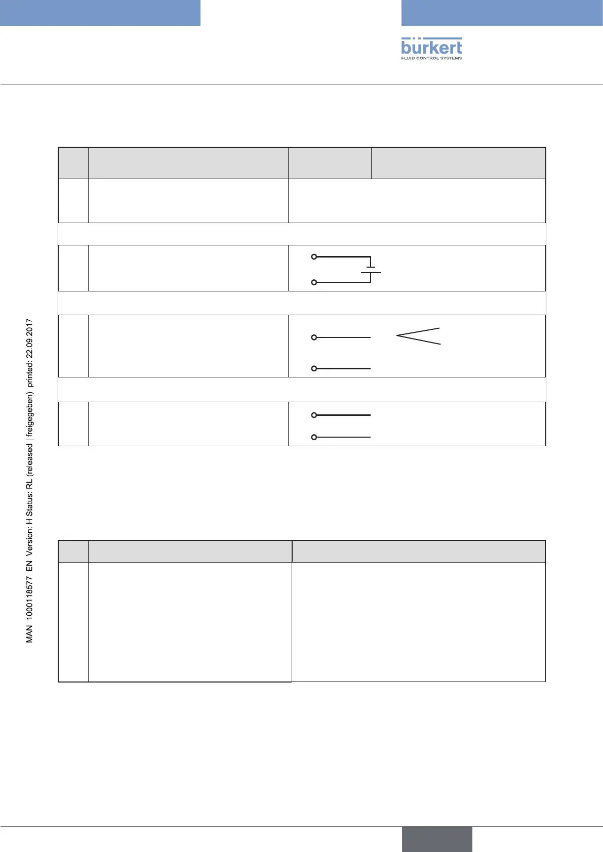
29.3. X1 - M12, 8-pole circular connector
Pin Configuration
On the device
side
External circuit / Signal level
1 not used
2 not used
Operating voltage
3 GND 3
24 V DC ± 10%
max. residual ripple 10%
4 +24 V 4
Input signals of the control centre (e.g. PLC)
5 Binary input + 5
+
0 – 5 V (log. 0)
10 – 30 V (log. 1)
6 Binary input – 6
GND (identical with Pin 3)
Output signals to the control centre (e.g. PLC) - (only used for binary output option)
7 Binary output 1 (referring to Pin 3) 7
0 – 24 V
8 Binary output 2 (referring to Pin 3) 8
0 – 24 V
Table 102: Pin assignment; X1 - M12, 8-pole circular connector; PROFIBUS DP
29.4. X2/X3 - M12, 5-pole socket/circular connector -
bus connection
Pin Configuration External circuit / Signal level
1 VP+5
Supply the terminating resistors
2 RxD/TxD-N
Received/transmitted data -N, A-line
3 DGND
Data transmission potential (earth to 5 V)
4 RxD/TxD-P
Received/transmitted data -P, B-line
5 Shielding
Shielding / protective earth
Table 103: Pin assignment; X2/X3 - M12, 5-pole circular connector/socket - bus connection, PROFIBUS DP