52
Installation
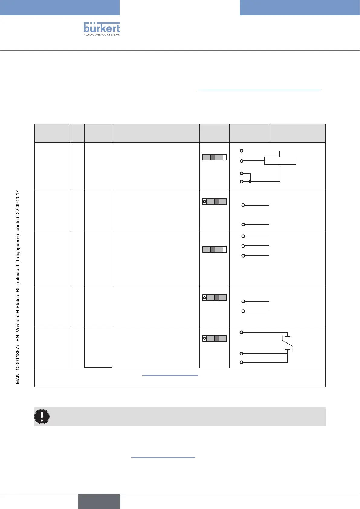
14.4. Connecting the process controller Type 8793
→ First connect the process controller as described in chapter “14.2. Connection of the positioner Type 8792”.
14.4.1. X5 - M8, 4-pole circular connector,
plug assignments of the process actual value input
Input type* Pin
Wire
colour**
Configuration
DIP
switches
On the
device side
External circuit
4 – 20 mA-
internally
supplied
1 brown +24 V transmitter supply
Switch
on left
1
2
3
4
Transmitter
GND
2 white Output from transmitter
3 blue GND (identical with GND
operating voltage)
4 black Bridge to GND (Pin 3)
4 – 20 mA-
externally
supplied
1 brown not used
Switch
on right
2 white Process actual + 2
4 - 20 mA
3 blue not used
4 black Process actual – 4
GND 4 - 20 mA
Frequency-
internally
supplied
1 brown +24 V sensor supply
Switch
on left
1
+24 V
2 white Clock input + 2 Clock +
3 blue Clock input – (GND) 3 Clock – / GND
(identical with GND
operating voltage)
4 black not used
Frequency-
externally
supplied
1 brown not used
Switch
on right
2 white Clock input + 2
Clock +
3 blue Clock input – 3 Clock –
4 black not used
Pt 100
(see infor-
mation
below)
1 brown not used
Switch
on right
2
3
4
Pt 100
2 white Process actual 1 (power supply)
3 blue Process actual 3 (GND)
4 black Process actual 2 (compensation)
* Can be adjusted via software (see chapter “21. Start-up sequence”).
** The indicated colors refer to the connection cable available as an accessory (918718).
Table 16: Pin assignment; X5 - M8, 4-pole circular connector - process actual value input
Connect the Pt 100 sensor via 3 cables for cable compensation reasons. It is essential to bridge terminal
3 and terminal 4 on the sensor.
When the operating voltage is applied, the process controller is operating.
→ Now make the required basic settings and actuate the automatic adjustment of the process controller. The
procedure is described in chapter “21. Start-up sequence”.