210
DeviceNet
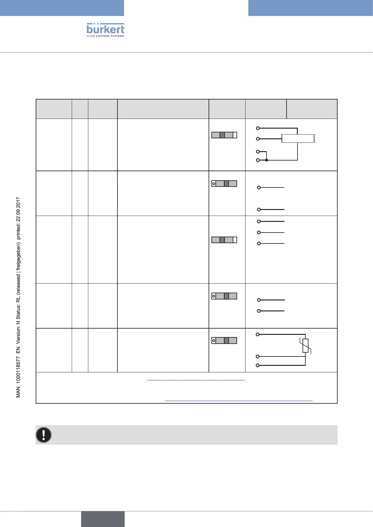
32.6. X5 - M8, 4-pole circular connector - process actual
value (Type 8793 only)
Input type* Pin
Wire
colour **
Configuration
DIP
switches***
On the
device side
External circuit
4 – 20 mA
- internally
supplied
1 brown +24 V transmitter supply
Switch on
left
1
2
3
4
Transmitter
GND
2 white Output from transmitter
3 blue GND (identical with the GND
operating voltage)
4 black Bridge after GND (Pin 3)
4 – 20 mA
- externally
supplied
1 brown not used
Switch on
right
2 white Process actual + 2
4 – 20 mA
3 blue not used
4 black Process actual – 4
GND 4 – 20 mA
Frequency
- internally
supplied
1 brown +24 V sensor supply
Switch on
left
1
+24 V
2 white Clock input + 2 Clock +
3 blue Clock input – (GND) 3 Clock – / GND
(identical with
the GND oper-
ating voltage)
4 black not used
Frequency
- externally
supplied
1 brown not used
Switch on
right
2 white Clock input + 2
Clock +
3 blue Clock input – 3 Clock –
4 black not used
Pt 100
(see infor-
mation
below)
1 brown not used
Switch on
right
2
3
4
Pt 100
2 white Process actual 1 (power supply)
3 blue Process actual 3 (GND)
4 black Process actual 2 (compensation)
* Can be adjusted via software (see chapter “23.1. INPUT - Setting the input signal”).
** The indicated colors refer to the connection cable available as an accessory (918 718).
*** The switch is inside the device on the PCB (see “Figure 25: Location of the switch; symbols for switch position”).
Table 118: Plug assignments; X5 - M8, 4-pole circular connector - process actual value input; DeviceNet
Connect the Pt 100 sensor via 3 cables for cable compensation reasons. It is essential to bridge Pin 3
and Pin 4 on the sensor.