54
Installation
Procedure:
→ Unscrew the 4 screws on the housing cover and remove the cover.
The screw-type terminals are now accessible.
→ Connect Type 8792/8793.
The procedure is described in the following chapters.
for Type 8792: chapter “15.2. Terminal assignment for cable gland - positioner Type 8792”
for Type 8793: chapter “15.3. Terminal assignment for cable gland - process controller Type 8793”
15.2. Terminal assignment for cable gland - positioner
Type 8792
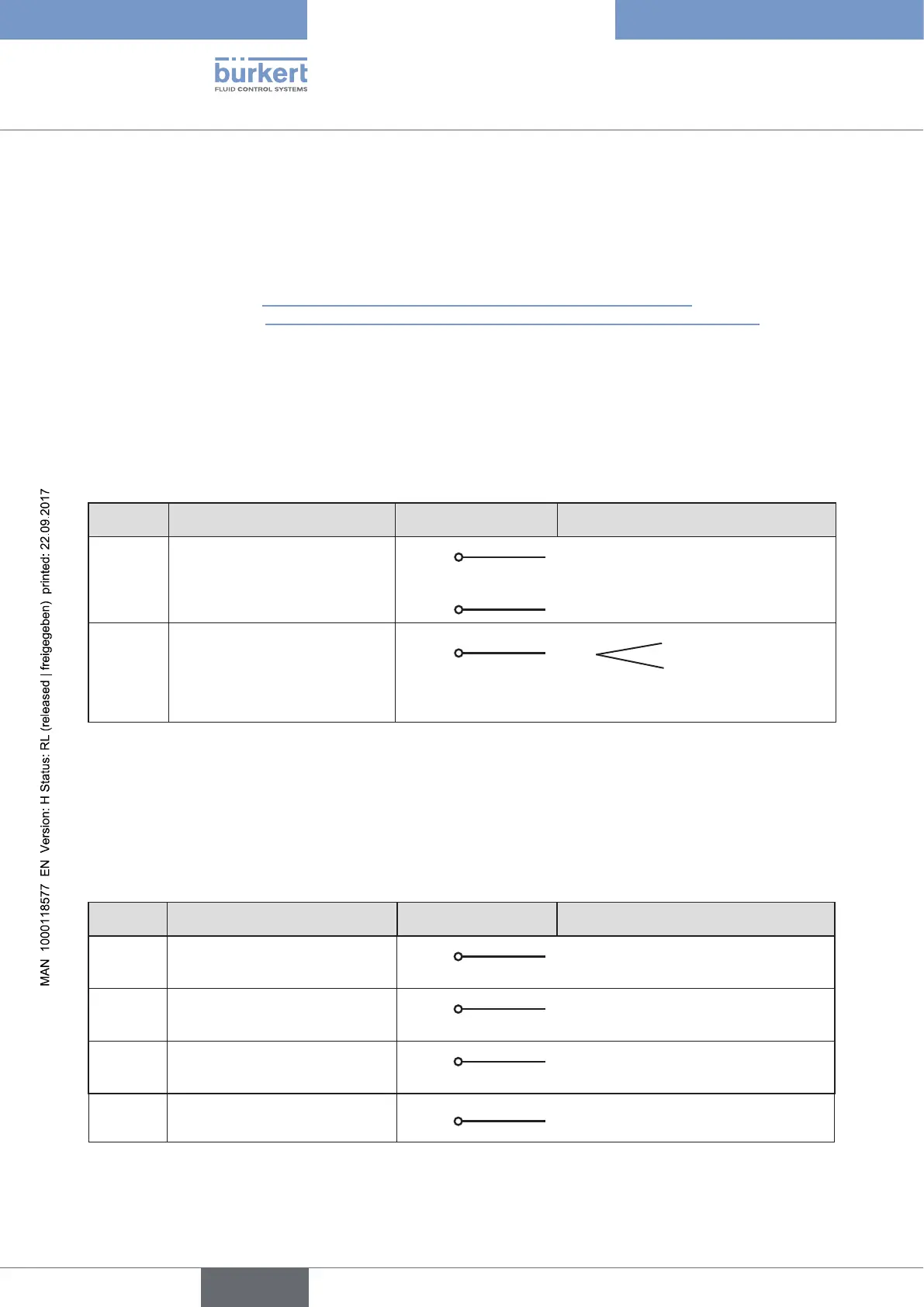
15.2.1. Input signals from the control centre (e.g. PLC)
Terminal Configuration On the device side External circuit / Signal level
11 + Set-point value +
11 +
+ (0/4 – 20 mA or 0 – 5 / 10 V)
completely galvanically isolated
12 – Set-point value GND
12 –
GND set-point value
81 +
Binary input +
81 +
+
0 – 5 V (log. 0)
10 – 30 V (log. 1)
specific to operating voltage GND
(terminal GND)
Table 17: Terminal assignment; input signals of the control centre
15.2.2. Output signals to the control centre (e.g. PLC)
(required for analogue output and/or binary output option
only)
→ Connect terminals according to the model (options) of the positioner.
Terminal Configuration On the device side External circuit / Signal level
83 + Binary output 1
83 +
24 V / 0 V, NC / NO specific to
operating voltage GND (terminal GND)
85 + Binary output 2
85 +
24 V / 0 V, NC / NO specific to
operating voltage GND (terminal GND)
31 + Analogue feedback +
31 +
+ (0/4 – 20 mA or 0 – 5 / 10 V)
completely galvanically isolated
32 – Analogue feedback GND
32 –
GND Analogue feedback
Table 18: Terminal assignment; output signals to the control centre