208
DeviceNet
32.3. X1 - M12, 8-pole circular connector
Pin Configuration
On the device
side
External circuit / Signal level
1 not used
2 not used
Operating voltage
3 GND 3
24 V DC ± 10%
max. residual ripple 10%
4 +24 V 4
Input signals of the control centre (e.g. PLC)
5 Binary input + 5
+
0 – 5 V (log. 0)
10 – 30 V (log. 1)
6 Binary input – 6
GND (identical with Pin 3)
Output signals to the control centre (e.g. PLC) - (only used for binary output option)
7 Binary output 1 (referring to Pin 3) 7
0 – 24 V
8 Binary output 2 (referring to Pin 3) 8
0 – 24 V
Table 114: Pin assignment; X1 - M12, 8-pole circular connector DeviceNet
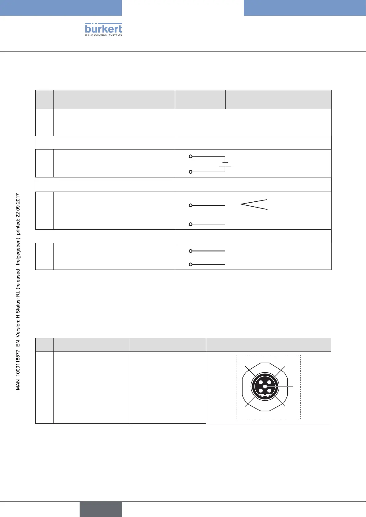
32.4. X3 - M12, 5-pole circular connector - bus
connection
Pin Signal Colour Configuration
1 Shielding not used
2
3
4
1
5
2 V + not used
3 V – not used
4 CAN H white
5 CAN L blue
Table 115: Pin assignment; X3 - M12, 5-pole circular connector - bus connection; DeviceNet