ID-DCU-MARINE-2.2.2, ©ComAp – June 2015 - 21 -
ID-DCU-MARINE-2.2.2.pdf
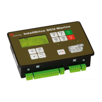
How to establish ID-DCU MARINE to I-RD-CAN-ID-DCU-MARINE connection
Following screen appears after I-RD-CAN-ID-DCU-MARINE power supply is switched on and there is no
connection to ID-DCU MARINE established.
1. Connect selected communication line between ID-DCU MARINE controller and I-RD-CAN-ID-DCU-
MARINE panel.
2. Switch ID-DCU MARINE and I-RD-CAN-ID-DCU-MARINE power supply on.
3. After I-RD-CAN-ID-DCU-MARINE Initialization screen appears: Use front panel / buttons to
change Controller address in the range 1 to 8 or AUTO. I-RD-CAN-ID-DCU-MARINE automatically
increases the controller address and tries to open connection. This Controller address must
correspond to connected ID-DCU MARINE Basic setting: Controller address setpoint.
4. Use Page button to set I-RD-CAN-ID-DCU-MARINE connection type: CAN addr.1, CAN addr.2 or
RS232.
5. Then press Enter button to start data download. Message TRAYING … appears on the I-RD-CAN-
ID-DCU-MARINE screen. Unsuccessful attempt to read data is repeated each 15 sec.
6. The Programming bargraph appears on I-RD-CAN-ID-DCU-MARINE screen after connection is
opened.
7. Standard ID-DCU MARINE screen appears after complete configuration is loaded to I-RD-CAN-ID-
DCU-MARINE.
Hint:
To switch to Init screen press Page button for more than 2 sec when CFG table error message appears on
the I-RD-CAN-ID-DCU-MARINE screen.
 Loading...