User's Manual
358
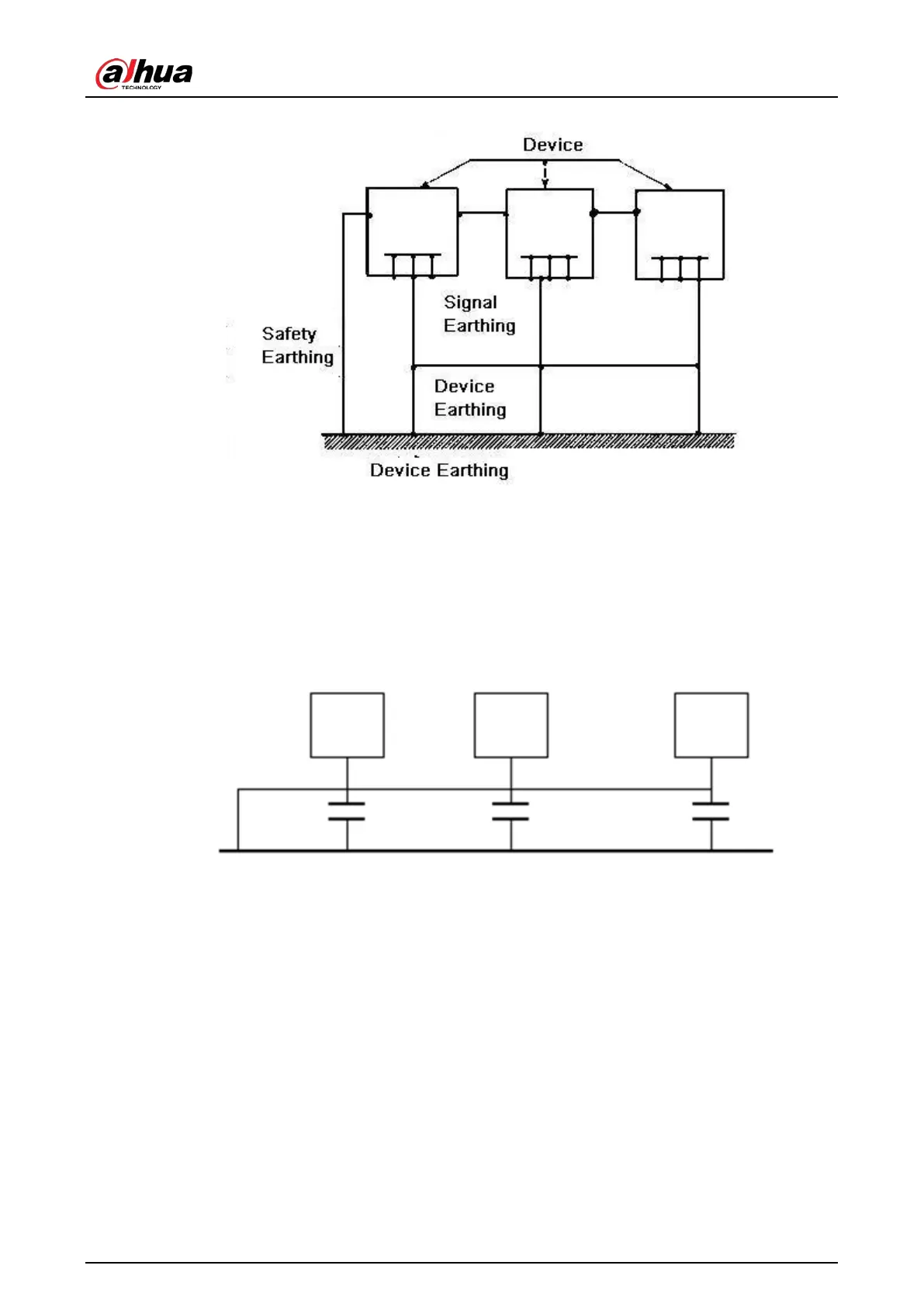
Appendix Figure 7-2 Multiple-point ground
●
Mixed ground
: The mix ground consists of the feature of the one-point ground and multiple-
point ground. For example, the power in the system needs to use the one-point ground mode
while the radio frequency signal requires the multiple-point ground. So, you can use the
following figure to earth. For the direct current (DC), the capacitance is open circuit and the
circuit is one-point ground. For the radio frequency signal, the capacitance is conducive and the
circuit adopts multiple-point ground.
Appendix Figure 7-3 Mixed ground
When connecting devices of huge size (the device physical dimension and connection cable is big
comparing with the wave path of existed interference), then there is possibility of interference when
the current goes through the chassis and cable. In this situation, the interference circuit path usually
lies in the system ground circuit.
When considering the earthing, you need to think about two aspects: One is the system
compatibility, and the other is the external interference coupling into the earth circuit, which results
in system error. For the external interference is not regular, it is not easy to resolve.
Appendix 7.3 Thunder Proof Ground Method in the Monitor
System
●
The monitor system shall have sound thunder proof earthing to guarantee personnel safety and
device safety.
 Loading...